Retention dual use bit holder

Active Publication Date: 2009-06-18
KERNODLE JR RICHARD VERNON
View PDF16 Cites 10 Cited by
  • Summary
  • Abstract
  • Description
  • Claims
  • Application Information

AI Technical Summary

Benefits of technology

[0010]In yet another exemplary embodiment of the present invention, the bit holder further comprises a base exterior havi

Problems solved by technology

These bits are considerably smaller than other such tools, like a drill, nail gun, or power saw, therefore, they can be easily mishandled or misp

Method used


Image

  • Retention dual use bit holder
  • Retention dual use bit holder
  • Retention dual use bit holder

Examples


Embodiment Construction

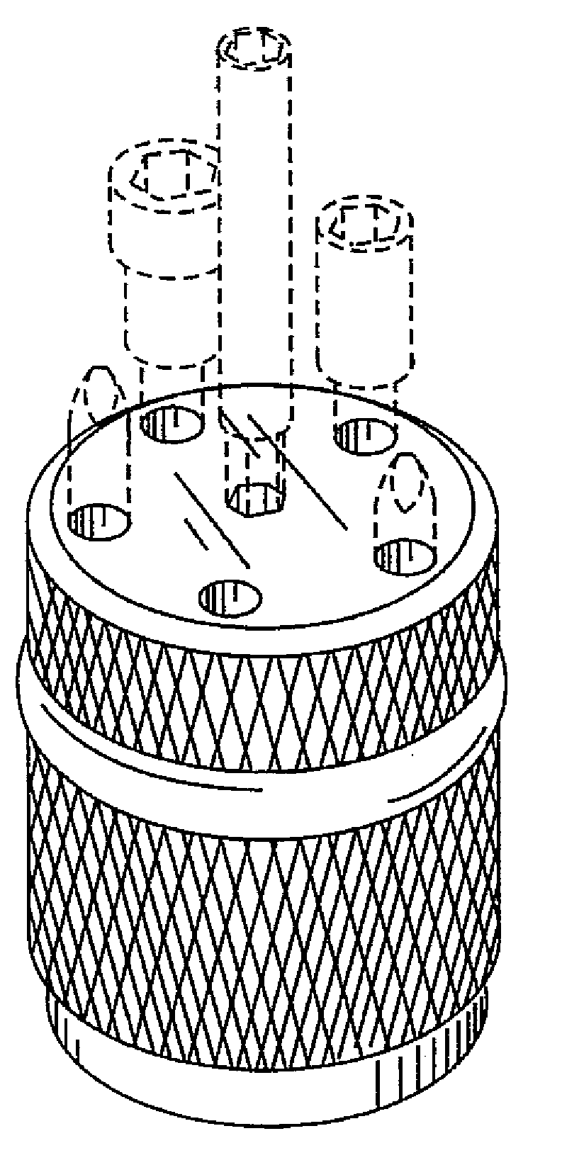
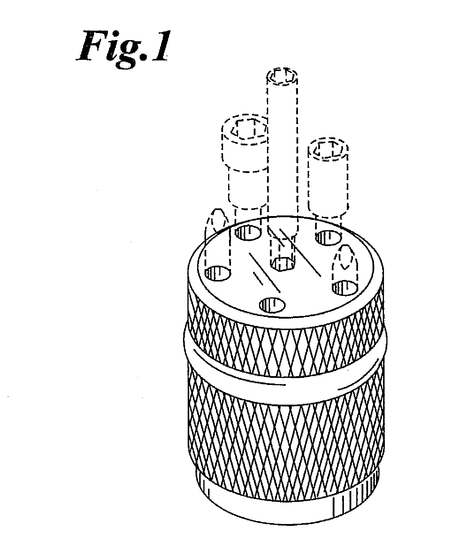
[0028]Referring now specifically to the drawings, an exemplary bit holder is illustrated in FIG. 1 and is shown generally at reference numeral 10. As illustrated, the device 10 has a cylindrical base 12 with a top portion 14 and a bottom portion 16. A magnetic member 18 is optionally engaged to the base 12. The magnetic member 18 allows the base 12 to be removably attached to a metallic surface for storage. Bits 20, disposed within longitudinally oriented bit compartments 22, protrude through the top portion 14 of the device 10, allowing the bits 20 to be grasped by a construction professional and removed from the base 12. The base 12 has an outer surface that is abrasive, allowing the user to easily grip the base 12 during use. The surface of the base 12 can be coated, fitted, milled or formed with any material, indentions, covering, or the like that increases coefficient of friction of the surface.

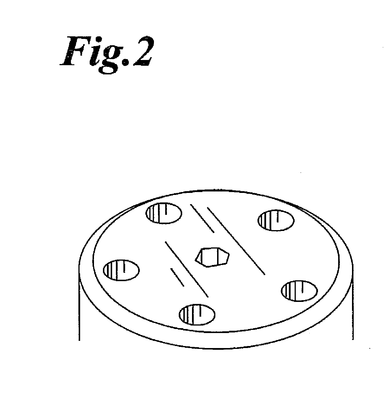
[0029]As shown in FIG. 2, the top portion 14 of the base 12 has a plurality of longi...


PUM


Abstract

A bit holder, comprising a base having a plurality of longitudinally oriented bit compartments for releasably storing multiple tool bits, a retention member positioned on the outside of the base for releasably retaining the tool bits within the base, and a magnetic member engaged with the base for allowing the base to be removably attached to a metal surface for storage.

Description

FIELD OF THE INVENTION[0001]The present invention relates generally to a bit holder, and more particularly, a bit holder that utilizes a retention member that exerts a tension force upon the bit for releasably retaining the bits within the holder.BACKGROUND OF THE INVENTION[0002]Bits are tools that may be attached to the end of a power tool, such as a drill, which supplies axial force and rotates the bits. The bits can serve a number of functions such as creating a hole in a surface, acting as the head of a screwdriver that mates with the head of the screw, drive a bolt, socket or the like. These bits are considerably smaller than other such tools, like a drill, nail gun, or power saw, therefore, they can be easily mishandled or misplaced on the job or in storage. In addition, on a construction job a worker could be required to use multiple bits that have to be interchanged to suit the particular construction purpose. It would be advantageous for the construction worker to be able t...

Claims


Application Information

Patent Timeline
IPC IPC(8): B65D85/30
CPCB25H3/003
Inventor KERNODLE, JR., RICHARD VERNON
Owner KERNODLE JR RICHARD VERNON
Why Eureka
Try Eureka