
Bottle storage device

a technology for storage devices and bottles, applied in the field of bottles, can solve the problems of comparatively low storage capacity of bottles storage devices, and achieve the effect of space-saving storag

Active Publication Date: 2009-06-18
OSANG BET GMBH
View PDF3 Cites 25 Cited by
  • Summary
  • Abstract
  • Description
  • Claims
  • Application Information

AI Technical Summary

Benefits of technology

[0006]The object of the invention is to provide a bottle storage device, which can easily be loaded and from which the stored material again can easily be unloaded while providing a high storage capacity in reference to the volume of the device and which can be produced in a cost-effective manner.
[0009]In an advantageous embodiment of the invention, the third support assembly part is provided with a front stopper projecting upwards in the area of its freely projecting end. In this way, the unintentional falling of bottles out of the bottle storage device at the removal side is prevented, while the stopper can be embodied so short that the removal of bottles is not hindered in the central area of the removal side.
[0010]Advantageously the bottles of the two rows of a double row are arranged on their support assemblies such that the bottles of the two rows are arranged off-set in reference to each other in the direction of the rows, with the bottle necks overlapping in the area of the central support assembly part, resulting in a space-saving storage.

Problems solved by technology

This is particularly disadvantageous when using the rack unit for sales display, because signets and product information are usually applied at the lateral surfaces of the goods to be displayed and customers want to access the selected goods without any delay in case of a positive decision for purchase.
This bottle storage device has a comparatively low storage capacity and each bottle must be inserted precisely into the holding parts which are formed relatively small.

Method used


Image

  • Bottle storage device
  • Bottle storage device
  • Bottle storage device

Examples


first embodiment

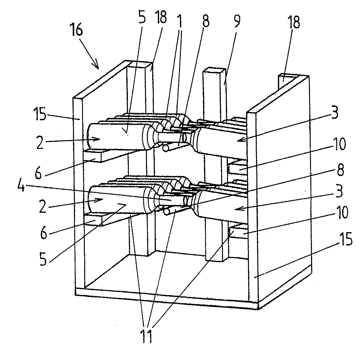
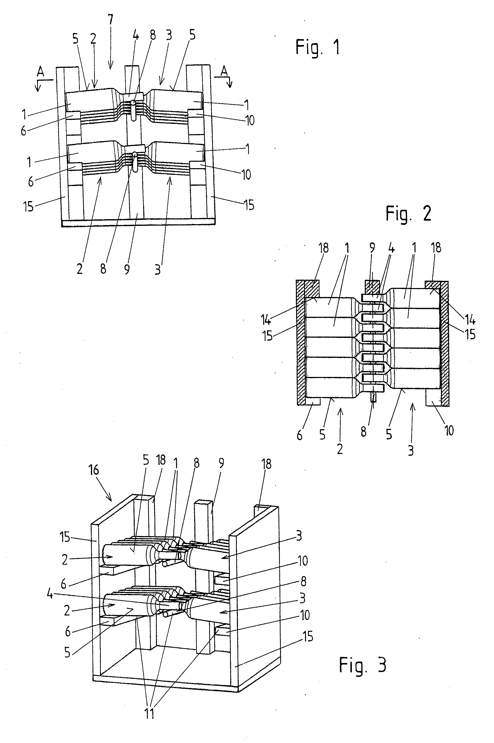
[0034]FIGS. 1 through 3 show the bottle storage device according to the invention for two double rows 7 of bottles 1, arranged one over top of the other, each of them resting on a support assembly 11 and formed by a first row 2 and a second row 3 of bottles 1.

[0035]The bottles 1 each comprise a bottom of the bottle, a cylindrical lateral surface 5, and a bottle neck 4 with its diameter being reduced in reference to the lateral surface 5.

[0036]The bottle storage device has a body 16 with two body side walls 15 and rear body parts. Here, the rear wall of the body is not embodied continuously but is formed by two rear wall-side parts 18 of the body, each extending towards the center and a rear wall-center part 9 of the body extending vertically between them. Each of the two rear wall-side parts 18 of the body is connected fixed to the corresponding side wall 15 of the body. The left rear wall-side part 18 of the body has a slightly greater thickness than the right rear wall-side part 1...

third embodiment

[0056]As clearly shown in the above description, this third embodiment of the support assembly 11 is suitable both to form an insertion part easily insertable into the body 16 of a bottle storage device and easily removable therefrom, as well as suitable to form an attachment suspended at a rear wall and removable therefrom.

fourth embodiment

[0057]a support assembly 11 is shown in FIGS. 16 through 19. Here, the first support assembly part 6 and the second support assembly part 10 are each formed from sheet metal. They could also comprise one or more appropriately shaped plastic parts. The lateral surface support sections 406 are essentially in the form of trapezoids (FIG. 19) in a top view. The first and second support assembly part 6, 10 and the third support assembly part 8 are connected to two rear round steel rods 19, extending parallel in reference to each other and vertically spaced apart from each other. At their ends at the removal side, the first support assembly part 6 and the second support assembly part 10 are each formed with a bend, having a relatively small curvature. The curvature of the sheet metal must be so small that a pin, serving as the rotation axis for a rotating body 23, can be held by such an end at the removal side.

[0058]At its rear end the sheet metal is bent around the lower one of the two r...


PUM


Abstract

A bottle storage device, particularly a bottle rack, is provided for at least one double row (7) including a first row (2) and a second row (3) of bottles (1) and resting on a support assembly (11), with each support assembly (11) having a first support assembly part (6) and a second support assembly part (10) for supporting the lateral surfaces (5) of the bottles (1), and a third support assembly part (8) is arranged between them for supporting the bottle necks (4) of the bottles (1), with the support assembly parts (6, 8, 10) each being spaced apart from each other. The third support assembly part (8) projects freely from a rear side of the bottle storage device, opposite the removal side, extending towards the removal side. Stops (14) are provided for the lateral surfaces (5) of the rearmost bottle (1) of the first and the second row (2, 3), which are off-set in reference to each other in a direction of the rows (2, 3).

Description

CROSS-REFERENCE TO RELATED APPLICATIONS[0001]This application is a continuation of International Application No. PCT / AT2007 / 000373, filed Aug. 1, 2007, which claims the benefit of Austrian Application No. A1484 / 2006, filed Sep. 6, 2006, both of which are incorporated herein by reference as if fully set forth.BACKGROUND[0002]The invention relates to a bottle storage device, particularly a bottle rack, for at one double row of bottles formed by a first row and a second row and supported on a support assembly, with each support assembly comprising a first support assembly part for supporting the lateral surfaces of the bottles of the first row and a second support assembly part for supporting the lateral surfaces of the bottles of the second row and a third support assembly part arranged therebetween to support the bottle necks of the bottles of both rows of the double row, with the respective support assembly parts being distanced from each other.[0003]Bottle storage devices, particul...

Claims


Application Information

Patent Timeline
IPC IPC(8): A47F7/00A47B73/00
CPCA47B73/00
Inventor BRIDA, HUBERT
Owner OSANG BET GMBH
Learn More