Phase locked loop circuit performing two point modulation and gain calibration method thereof

a phase lock and loop circuit technology, applied in the direction of angle modulation, electrical apparatus, pulse automatic control, etc., to achieve the effect of wide bandwidth and reduce lock tim

Inactive Publication Date: 2009-06-18
SAMSUNG ELECTRONICS CO LTD
View PDF4 Cites 37 Cited by
  • Summary
  • Abstract
  • Description
  • Claims
  • Application Information

AI Technical Summary

Benefits of technology

[0012]To solve the above and/or other problems, exemplary embodiments of the present invention provide a phase locked loop circuit that uses a loop filter that has a wide bandwidth to reduce a lock time during a calibration ...

Problems solved by technology

When the gains of the two routes are mismatched, however, it can be seen that in the P...

Method used


Image

  • Phase locked loop circuit performing two point modulation and gain calibration method thereof
  • Phase locked loop circuit performing two point modulation and gain calibration method thereof
  • Phase locked loop circuit performing two point modulation and gain calibration method thereof

Examples


Embodiment Construction

[0031]This application claims priority under 35 U.S. Section 119 to Korean Patent Application No. 10-2007-0112367, filed Nov. 5, 2007, in the Korean Intellectual Property Office, the disclosure of which is incorporated herein in its entirety.

[0032]The attached drawings for illustrating exemplary embodiments of the present invention are referred to in order to gain a sufficient understanding of the present invention, the merits thereof, and the objectives accomplished by the implementation of the present invention. Hereinafter, the present invention will be described in detail by explaining exemplary embodiments with reference to the attached drawings. Like reference numerals in the drawings denote like elements.

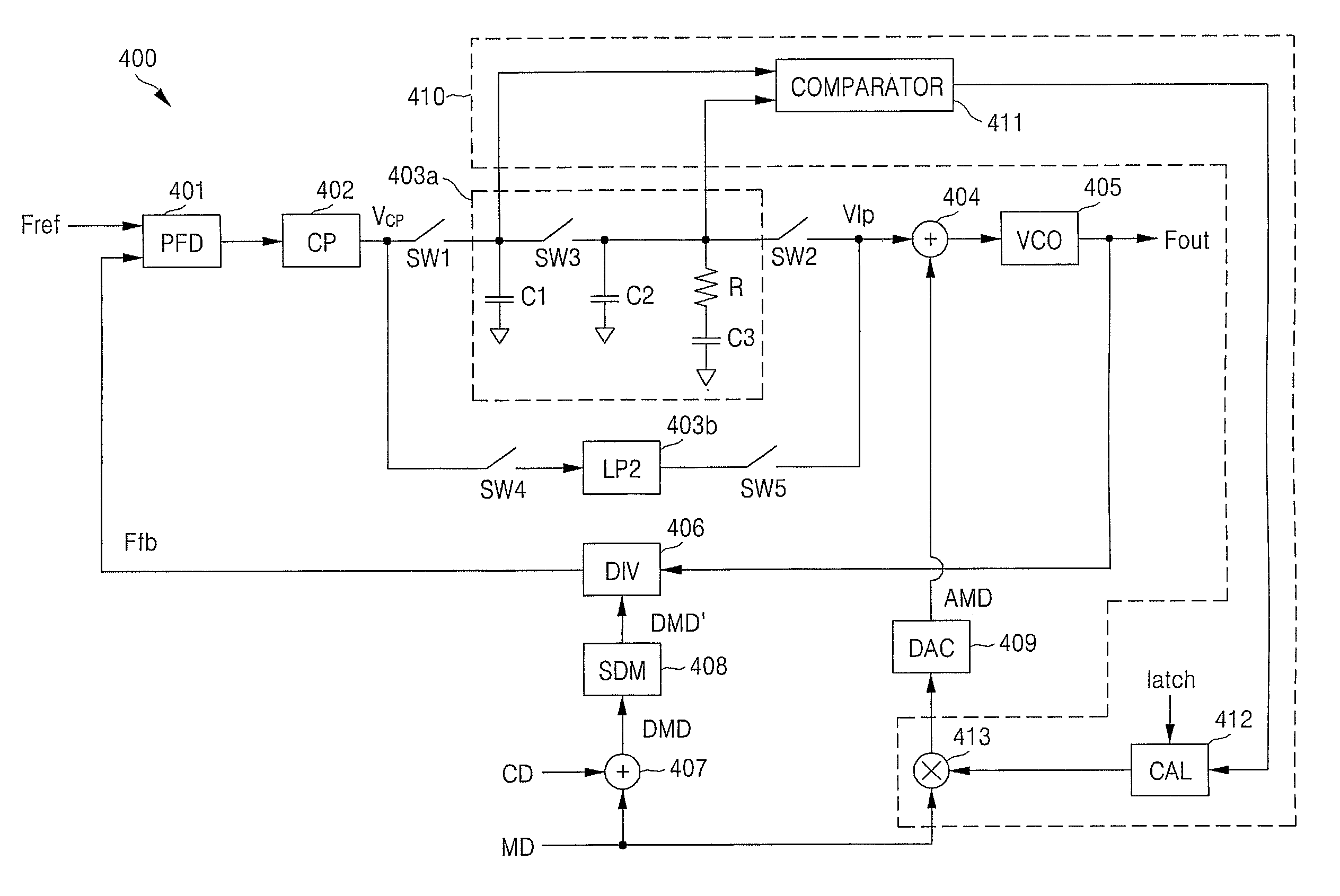
[0033]FIG. 4 is a circuit diagram of a PLL circuit 400 for performing gain calibration using an open loop, according to an exemplary embodiment of the present invention. Referring to FIG. 4, the PLL circuit 400 includes a phase / frequency detector (PFD) 401, a charge pump (CP)...


PUM


Abstract

A PLL circuit for two point modulation includes a first loop filter, a second loop filter, a plurality of switching devices, and a calibration module. The first loop filter filters an output voltage of a charge pump during a gain calibration operation. The second loop filter filters the output voltage of the charge pump during a normal operation. The first loop filter has a bandwidth wider than that of the second loop filter to perform a fast calibration by reducing a lock time. The operation of the first loop filter, the operation of the second loop filter, and the opening of the first loop filter are determined by the switching operations of the switching devices. The calibration module adjusts a gain of analog modulation data based on a frequency error accumulated in the first loop filter after the first loop filter is open during the gain calibration operation.

Description

CROSS REFERENCE TO RELATED APPLICATION[0001]This application claims priority under 35 U.S. Section 119 to Korean Patent Application No. 10-2007-0112367, filed Nov. 5, 2007, in the Korean Intellectual Property Office, the disclosure of which is incorporated herein in its entirety.BACKGROUND[0002]1. Technical Field[0003]The present disclosure relates to a phase locked loop circuit and a gain calibration method thereof and, more particularly, to a phase locked loop circuit that uses a loop filter having a wide bandwidth for a fast lock time during a calibration operation and calibrates a gain of analog modulation data based on a frequency error accumulated in the loop filter after the loop filter is open, and a method of calibrating the gain of the phase locked loop circuit.[0004]2. Discussion of Related Art[0005]Wireless communications devices such as cellular phones, personal digital assistants PDAs), personal computers (PCs), and broadcast equipment include transceivers for transcei...

Claims


Application Information

Patent Timeline
IPC IPC(8): H03L7/08
CPCH03C3/0925H03C3/0933H03C3/0941H03L7/1976H03C3/0991H03L7/0891H03L7/093H03C3/095H03L7/08
Inventor YU, HWA YEALKEUM, DONG JIN
Owner SAMSUNG ELECTRONICS CO LTD
Why Eureka
Try Eureka