Digital imager with dual rolling shutters

a digital imager and rolling shutter technology, applied in the field of digital imagers, can solve the problems of delay in reading out the data from the pixels, and affecting the accuracy of digital imagers

Inactive Publication Date: 2009-06-18
GOOGLE TECH HLDG LLC
View PDF47 Cites 50 Cited by
  • Summary
  • Abstract
  • Description
  • Claims
  • Application Information

AI Technical Summary

Problems solved by technology

However, when moving objects are being imaged, the rolling shutter can lead to artifacts.
In the time it takes the shutter to move across the entire pixel array, the objects can change position, thereby distorting the resulting image.
Unfortunately, this introduces a delay in reading out the data from the pixels.
This delay can create problems when a very small time interval is needed between acquisition of successive images or when a fast frame rate is needed.

Method used


Image

  • Digital imager with dual rolling shutters
  • Digital imager with dual rolling shutters
  • Digital imager with dual rolling shutters

Examples


Embodiment Construction

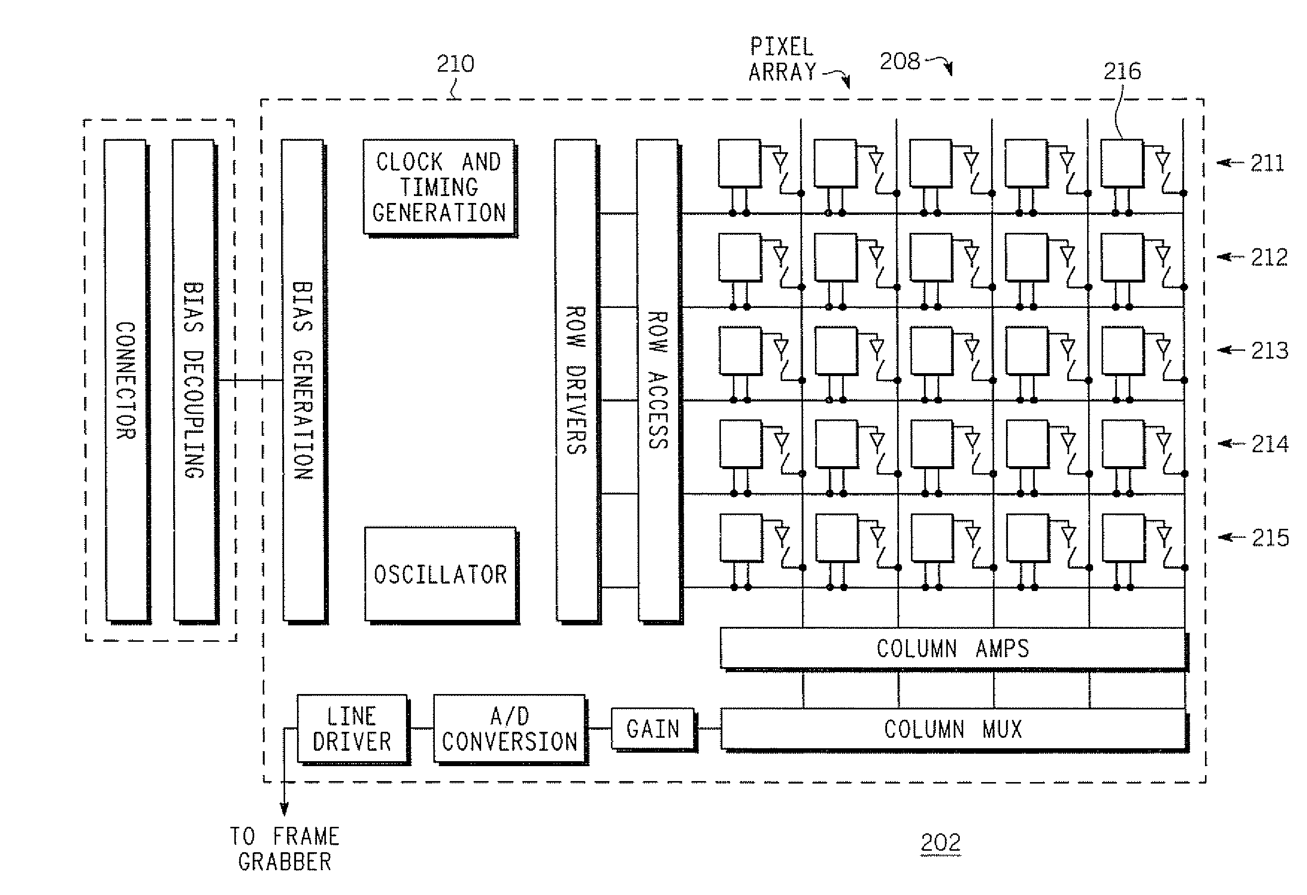
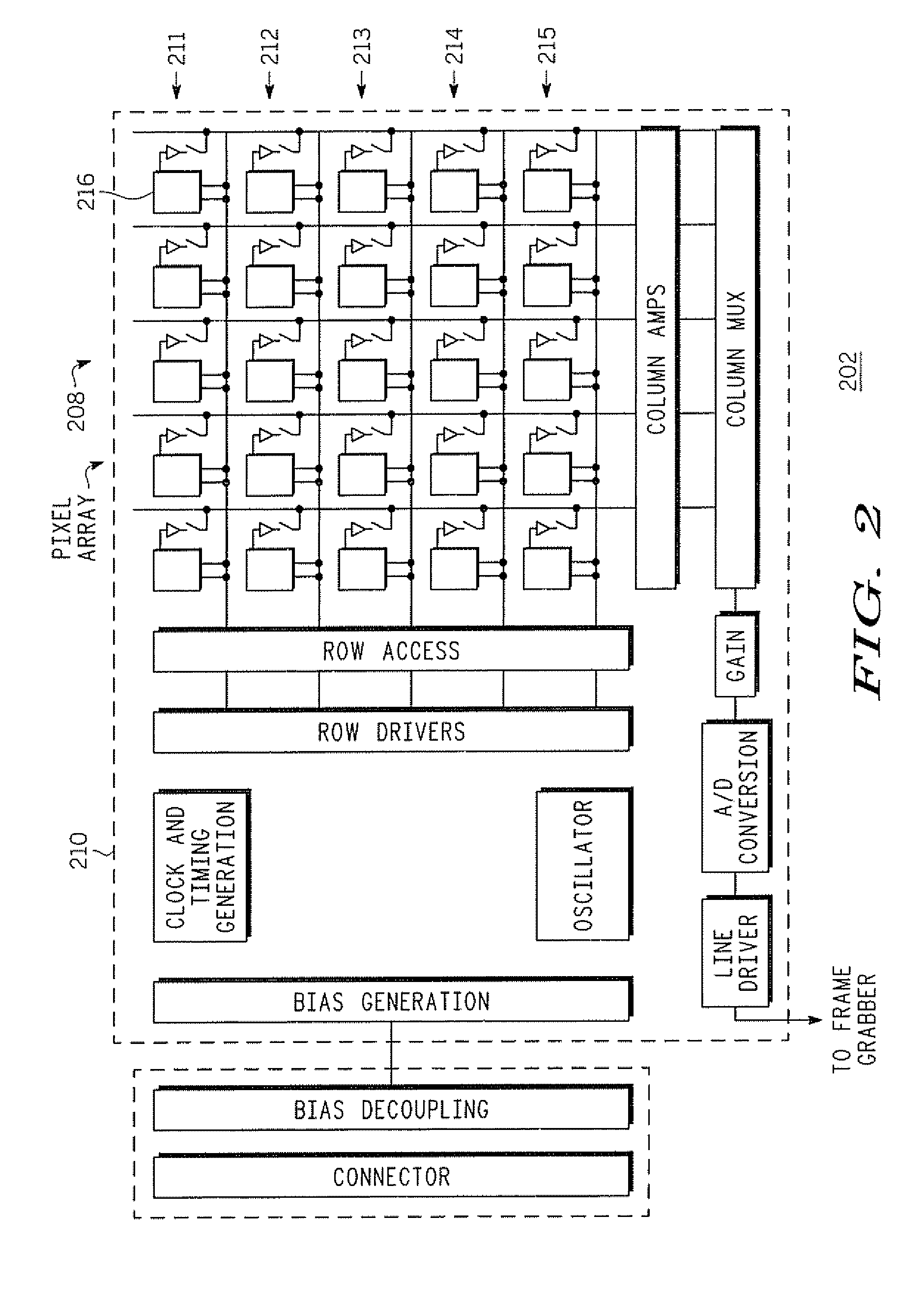
[0013]FIG. 2 illustrates a block diagram of one example of a digital imager 202. In some cases the digital imager 202 may be incorporated in a digital camera (still and / or video), cellular telephone, PDA, or any other electronic device that includes functionality in addition to that of imaging. The imager 202 may include an array of pixels 208 and processing circuitry 210 to direct the operation of the pixels. The pixels may be organized into rows or lines of pixels 211-215 aligned horizontally across the light sensitive portion of the sensor 202. Each pixel, such as a first pixel 216, acts as an optoelectric converter or photosensor that becomes electrically charged to a level directly proportional to the amount of light that strikes the pixel during a given time period, called the integration time. The pixels may be, for example, CMOS or CCD pixels. Each pixel in the array 208 may have its own amplifier and output circuitry to allow each pixel to be read out independently of the o...


PUM


Abstract

A method of forming an image of a moving object is provided. The method includes capturing a first digital image of a moving object using a first rolling shutter scanning in a first direction. Likewise, a second digital image of the moving object is captured using a second rolling shutter scanning in a second direction different from the first direction. The first and second digital images are processed to form a composite digital image of the moving image.

Description

FIELD OF THE INVENTION[0001]The invention relates generally to digital imagers, and more particularly to a digital imager with a rolling shutter.BACKGROUND OF THE INVENTION[0002]Digital cameras or imagers sample the original light that bounces off a subject to create a digital image. A digital camera may use a shutter in combination with a sensor to determine an exposure time and acquire the proper amount of light to capture a good image. The proper amount of light may come from accumulating ambient light over time until the proper amount of light is obtained to accurately render the chrominance and luminance in the image.[0003]In many digital CMOS imagers employing pixel arrays the optical integration time is controlled by the method known as “rolling shutter”. This approach utilizes at least two pointers, Reset and Read, that continuously move through the pixel array image frame from top to bottom by moving from row to row at predefined intervals. First, the Reset pointer 105 star...

Claims


Application Information

Patent Timeline
Patent Type & Authority Applications(United States)
IPC IPC(8): H04N3/14
CPCH04N5/23248H04N5/2329H04N5/37455H04N5/3532H04N5/374H04N5/2353H04N23/68H04N23/689H04N23/73H04N25/531H04N25/772H04N25/76
Inventor JOHN, GEORGE C.
Owner GOOGLE TECH HLDG LLC
Why Eureka
Try Eureka