Method to compensate the effect of the rolling shutter effect

Inactive Publication Date: 2011-11-03
ECOLE POLYTECHNIQUE FEDERALE DE LAUSANNE (EPFL)
View PDF1 Cites 50 Cited by
  • Summary
  • Abstract
  • Description
  • Claims
  • Application Information

AI Technical Summary

Benefits of technology

[0018]The purpose of the present application is to propose a method to compensate the effect of the rolling shutter effect. It is then proposed a method to cre

Problems solved by technology

Nevertheless, the inferior cost of manufacturing of the CMOS sensors can be explained due to technological compromises of which Rolling Shutter is a part and is employed on a wide range of movie cameras, starting from the sensors integrated in the mobile phones to the high end camcorders.
Both types of defects are found in practice.
The rolling shutter indeed disrupts the traditional methods of 3D from the video because it distorts the objects observed during the movements of the robot, thus introducing additional noise in the measures taken from the images.
Nevertheless, the proposed methods are used to correct images acquired by the camera only in case of full knowledge of the movement of the camera and the 3D depth of the points observed, which is not practical for generic imaging applications (and is already a strong constraint for the robotics in a controlled environment).
General public imagers: The interest of researchers for the correction of rolling shutter in consumer applications is also quite limited since only 2 teams have published works on this subject.
However, the panel of cases processed is limited to simple movements of the camera (translation, zoom) because of the complexity of expressions and calculation inaccuracies.
Moreover, most of the effort seems to have been put in producing a visually plausible image inte

Method used


Image

  • Method to compensate the effect of the rolling shutter effect
  • Method to compensate the effect of the rolling shutter effect
  • Method to compensate the effect of the rolling shutter effect

Examples


Embodiment Construction

[0032]Different methods of correcting the rolling shutter presented above consider only the geometric aspect of image formation, either as a projection of a 3D scene on the 2D surface of the sensor either as a result of 2D-2D transformation between successive frames.

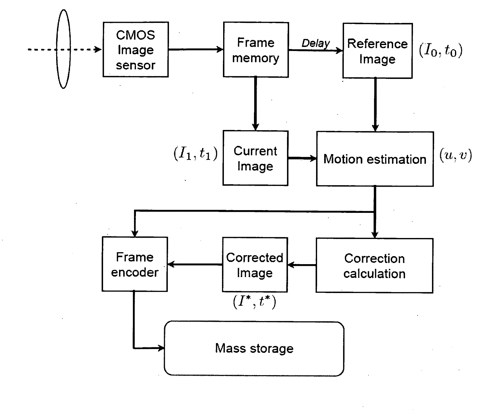
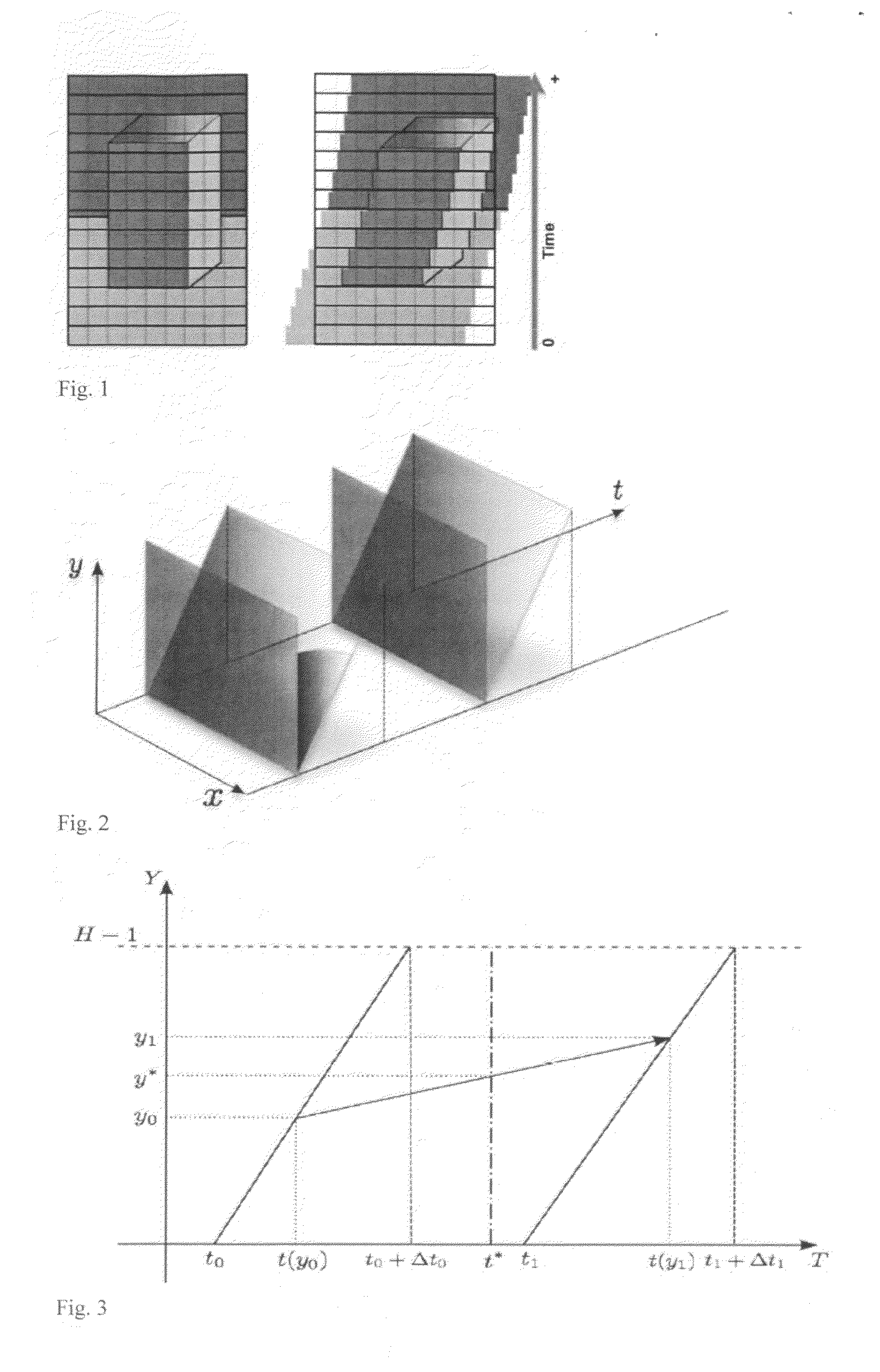
[0033]One of the features of the invention is to approach the problem from a different point of view, by considering the available image data in a 3D space where the 3 dimensions are given the 2 dimensions of the images (abscissa and ordinate) plus time. Indeed, capturing a correct image of “CCD” type is equivalent to measure the intensity of light on the sensor plane at a fixed time t: It is therefore a vertical plane in this 3D space abscissa, ordinate, time (x, y, t) (FIG. 2, perpendicular frame).

[0034]CMOS imagers, meanwhile, capture a 2D image (x, y) as well, but each line corresponds to different moments in time. These time instants are distributed linearly between the start and the end of the acquisition of an ima...


PUM


Abstract

A method to create a video sequence of a plurality of resultant images is disclosed. The video sequence is produced from images originating from a rolling shutter acquisition sensor.

Description

INTRODUCTION[0001]The present invention concerns the field of image acquisition by CMOS sensors and in particular is directed to the correction of the Rolling Shutter effect.BACKGROUND ART[0002]For several years, the CCD and CMOS technologies have been used to equip the sensor of digital still or animated imagery devices. Initially more performing, the CCD sensors have gradually been supplanted by the CMOS sensors that present a superior quality / price ratio. Nevertheless, the inferior cost of manufacturing of the CMOS sensors can be explained due to technological compromises of which Rolling Shutter is a part and is employed on a wide range of movie cameras, starting from the sensors integrated in the mobile phones to the high end camcorders.[0003]More precisely, today a digital imagery sensor (CCD or CMOS) is made of a 2D arrangement (commonly called matrix) of photosensitive elements (or pixels), usually according to a rectangular grid. Every photosensitive element converts the in...

Claims


Application Information

Patent Timeline
IPC IPC(8): H04N5/335
CPCH04N5/2329H04N23/689
Inventor D'ANGELO, EMMANUEL PIERRE AIMEVANDERGHEYNST, PIERRE
Owner ECOLE POLYTECHNIQUE FEDERALE DE LAUSANNE (EPFL)
Why Eureka
Try Eureka