Imaging device and imaging method

a technology of imaging device and output image, which is applied in the field of imaging device and imaging method, can solve the problems of generating dynamic distortion (focal plane distortion) and achieve the effect of suppressing the deterioration of the frame rate of the output image and reducing the distortion of the output imag

Inactive Publication Date: 2017-08-17
PANASONIC INTELLECTUAL PROPERTY MANAGEMENT CO LTD
View PDF0 Cites 50 Cited by
  • Summary
  • Abstract
  • Description
  • Claims
  • Application Information

AI Technical Summary

Benefits of technology

[0017]According to the present disclosure, even in a case of using the image sensor of the rolling shutter system, it is po

Problems solved by technology

Furthermore, as illustrated in FIG. 14, when the image sensor of the rolling shutter system is used, since the exposure start timings of the image sensor element at the upper part

Method used


Image

  • Imaging device and imaging method
  • Imaging device and imaging method
  • Imaging device and imaging method

Examples


modification example

in the Present Embodiment

[0136]Next, an example of monitoring camera 10P that not only emits the IR lighting when capturing the IR image which is the non-visible light image but also emits white LED lighting when capturing the RGB image which is the visible light image will be described as a modification example in the present embodiment with reference to the drawings.

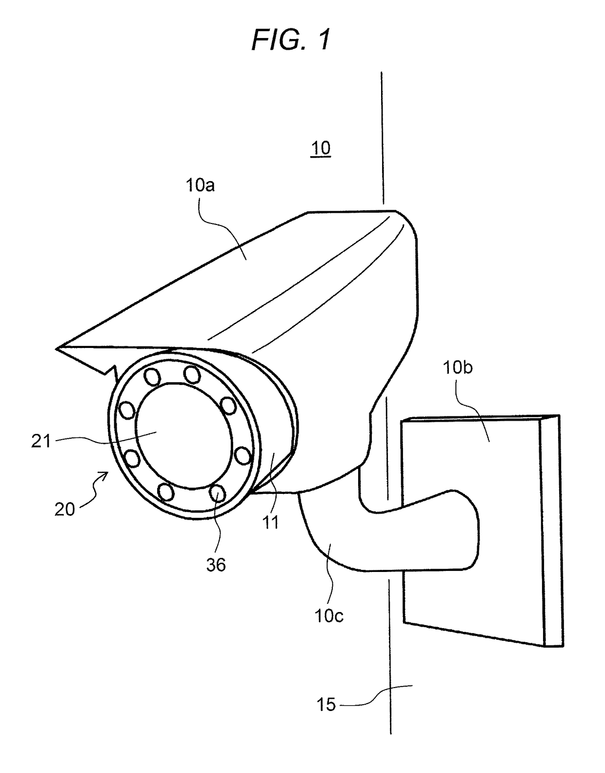
[0137]FIG. 10 is a schematic diagram illustrating an example of an external view of monitoring camera 10P in the modification example in the present embodiment. In the description of monitoring camera 10P illustrated in FIG. 10, the same reference marks will be given to the same configurations of monitoring camera 10 illustrated in FIG. 1, and the description thereof may be simplified or may be omitted, and the different points will be described. In FIG. 10, in imaging section 20 of monitoring camera 10P, four white LED sections 36P are provided between IR_LED section 36 and IR_LED section 36.

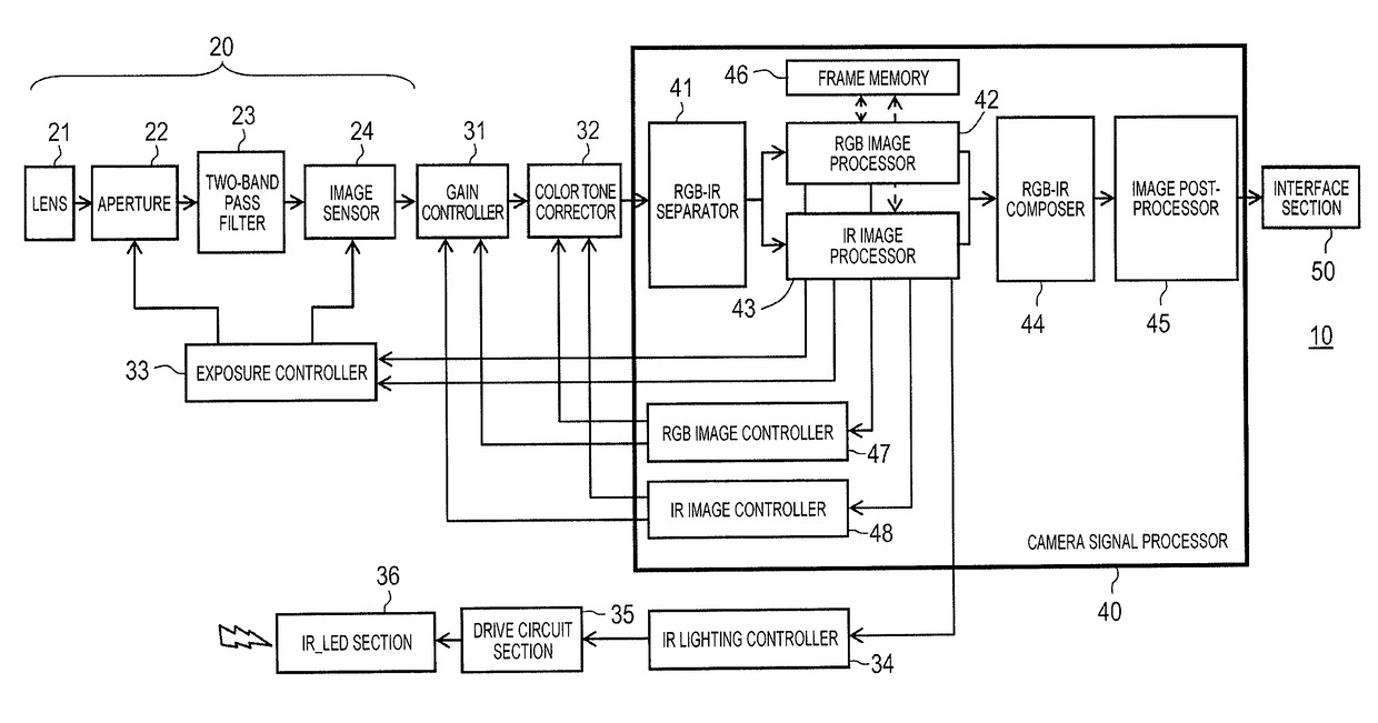
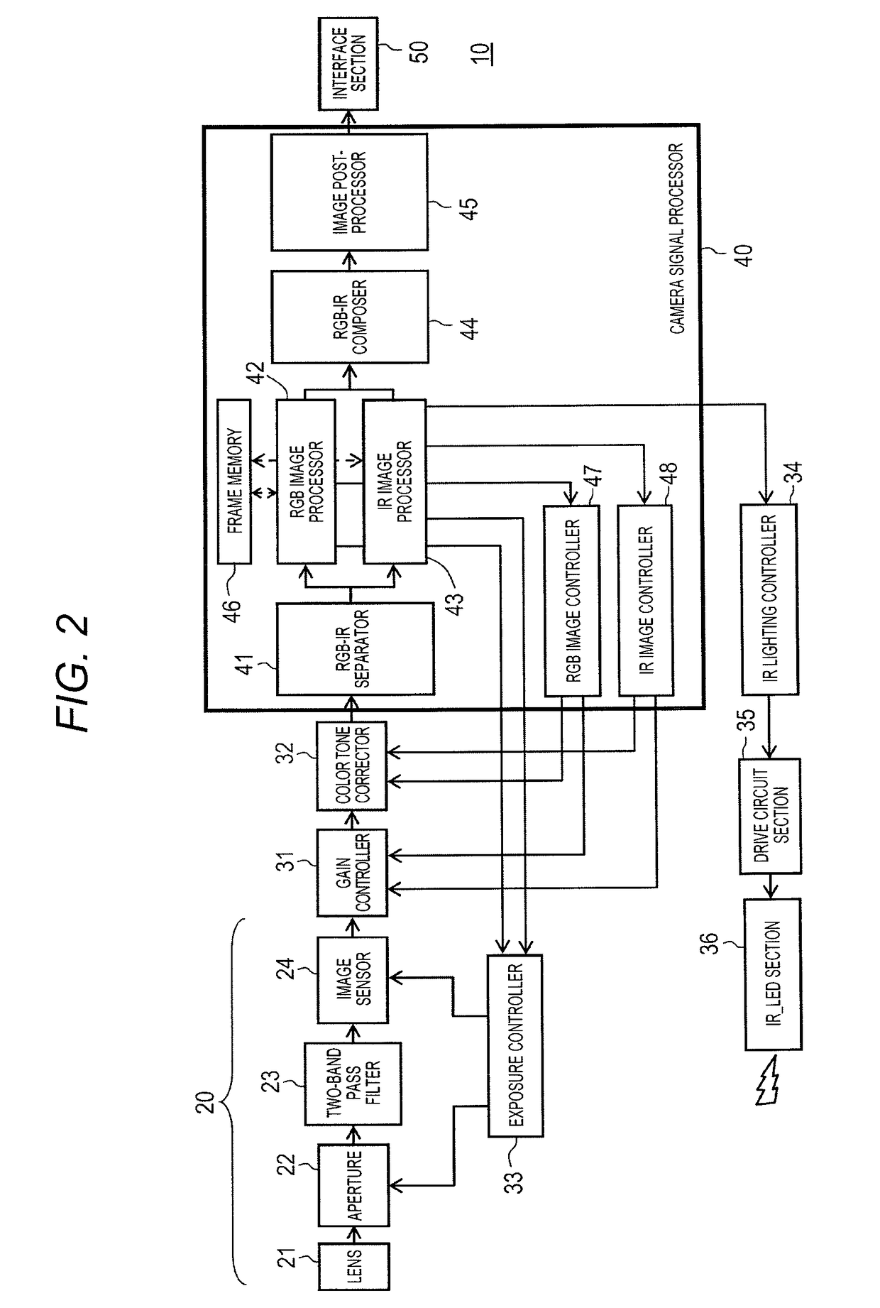
[0138]FIG. 11 is a block d...


PUM


Abstract

An imaging device includes an imaging section including an imaging sensor section of a rolling shutter system, a condition designator that sets an imaging condition using first auxiliary light which is non-visible light as an imaging condition for the imaging section and an imaging condition using visible light with the first auxiliary light as non-emitted light, and alternately designates the imaging condition and a light emission condition of the first auxiliary light at a cycle of at least two frames in a time division basis, a first light emitter that emits the first auxiliary light according to the light emission condition; and an image composer that composes a non-visible light image captured by the imaging section under the imaging condition using the first auxiliary light during a first period in which the first auxiliary light is emitted and a visible light image captured by the imaging section under the imaging condition using the visible light during a second period subsequent to the first period.

Description

TECHNICAL FIELD[0001]The present disclosure relates to an imaging device and an imaging method for capturing an image.BACKGROUND ART[0002]Recent years, an imaging system including a color camera that captures a color (red, green, and blue: RGB) image and a NIR camera that captures a NIR (Near Infrared) image, and a half mirror is known (for example, refer to NPL 1). In the imaging system disclosed in NPL 1, in a case where a color image is captured, a flash that emits near-infrared (NIR) rays to a subject is not used, and in a case where the NIR image is captured, the above-described flash is used.[0003]In the imaging system disclosed in NPL 1, light from the subject is divided toward two directions by the half mirror. The light divided toward two directions is imaged by the color camera and the NIR camera, and then, an RGB image and the NIR image are obtained. The RGB image is a color image. The NIR image is one of the images captured by emitting the infrared (NIR) rays and is a mo...

Claims


Application Information

Patent Timeline
IPC IPC(8): H04N5/235H04N5/217H04N5/445H04N5/33H04N5/225
CPCH04N5/2352H04N5/332H04N5/2256H04N9/097H04N5/2258H04N5/217H04N9/735H04N5/44504G03B7/091G03B15/05H04N23/56H04N23/45H04N23/70H04N23/11H04N23/72H04N23/81H04N23/16H04N23/88
Inventor TANAKA, SHOGOTABEI, KENJI
Owner PANASONIC INTELLECTUAL PROPERTY MANAGEMENT CO LTD
Why Eureka
Try Eureka