Heat-dissipating apparatus

Active Publication Date: 2009-06-18
SL SEOBONG
View PDF14 Cites 37 Cited by
  • Summary
  • Abstract
  • Description
  • Claims
  • Application Information

AI Technical Summary

Benefits of technology

[0014]However, aspects of the present invention are not restricted to the one set forth herein. The above and other aspects and features of the present invention will bec

Problems solved by technology

However, temperature remains a major challenge in the adoption of LEDs as a light source for vehicle lamps.
As the performance of LEDs improves, the LEDs emit heat at higher temperatures, and the heat at higher temperatures reduces the performance of

Method used


Image

  • Heat-dissipating apparatus
  • Heat-dissipating apparatus
  • Heat-dissipating apparatus

Examples


Embodiment Construction

[0025]Advantages and features of the present invention and methods of accomplishing the same may be understood more readily by reference to the following detailed description of exemplary embodiments and the accompanying drawings. The present invention may, however, be embodied in many different forms and should not be construed as being limited to the embodiments set forth herein. Rather, these embodiments are provided so that this disclosure will be thorough and complete and will fully convey the concept of the invention to those skilled in the art, and the present invention will only be defined by the appended claims. Like reference numerals refer to like elements throughout the specification.

[0026]In some embodiments, well-known processing processes, well-known structures and well-known technologies will not be specifically described in order to avoid ambiguous interpretation of the present invention.

[0027]The terminology used herein is for the purpose of describing particular e...


PUM


Abstract

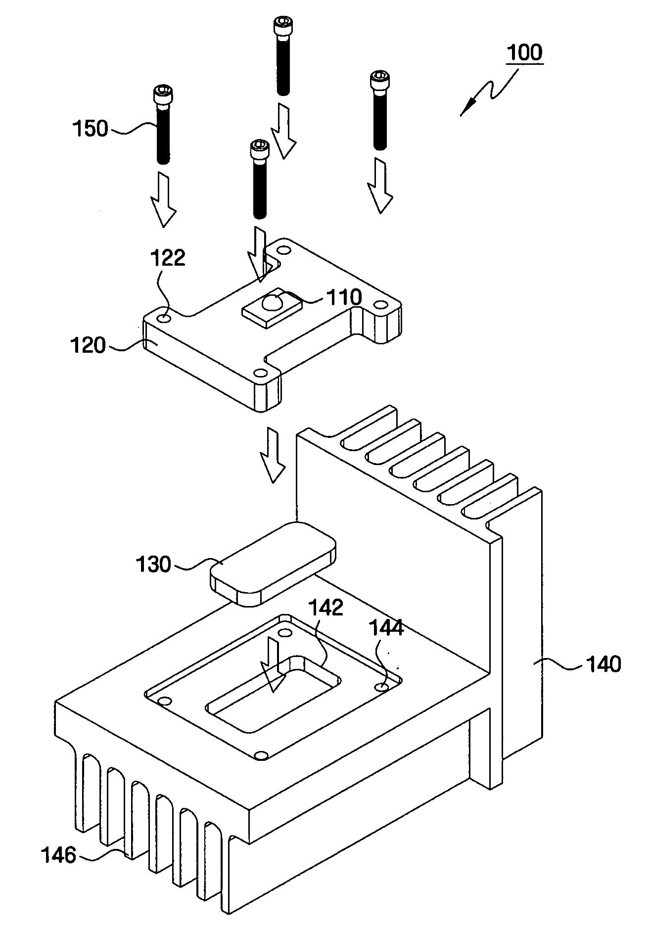
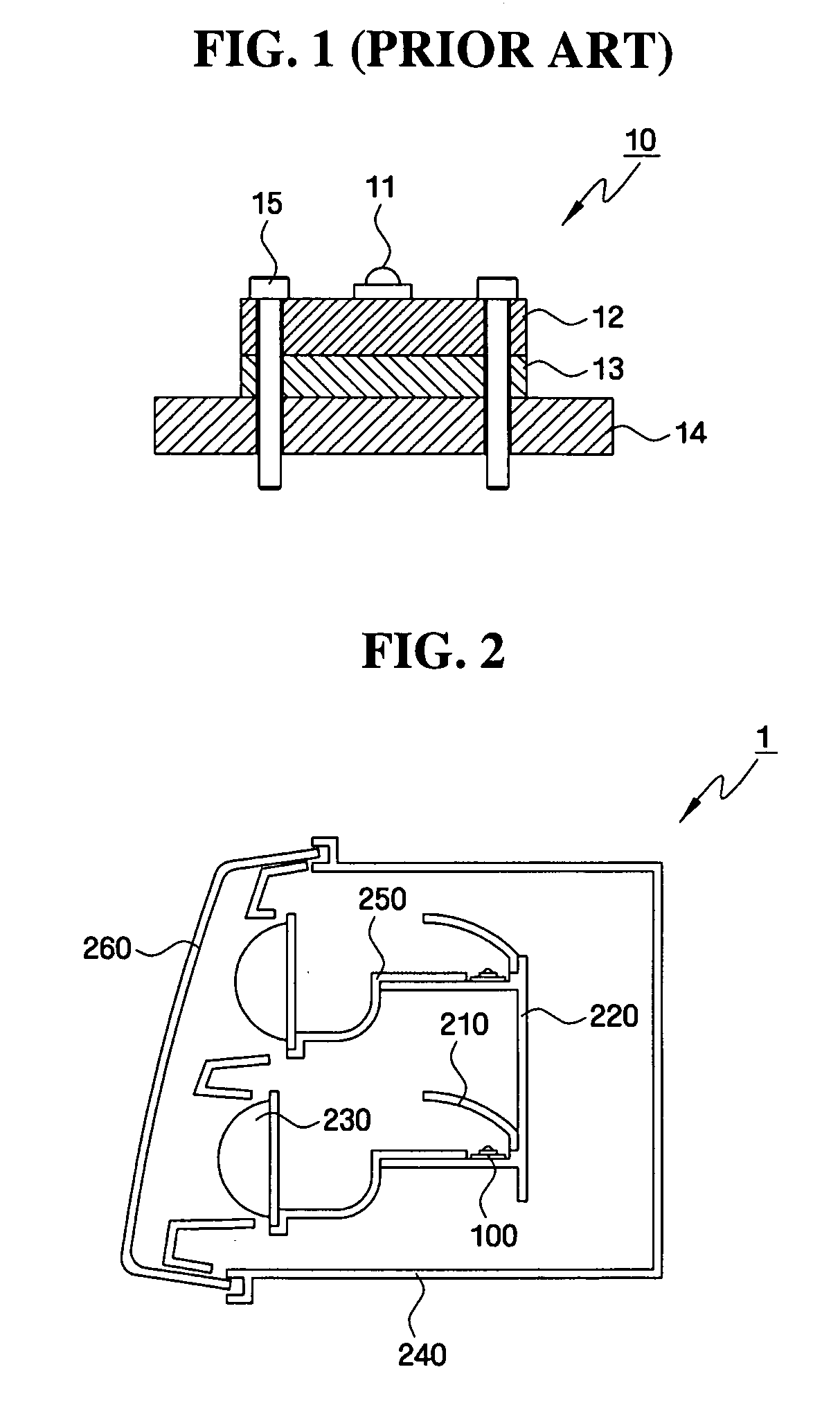
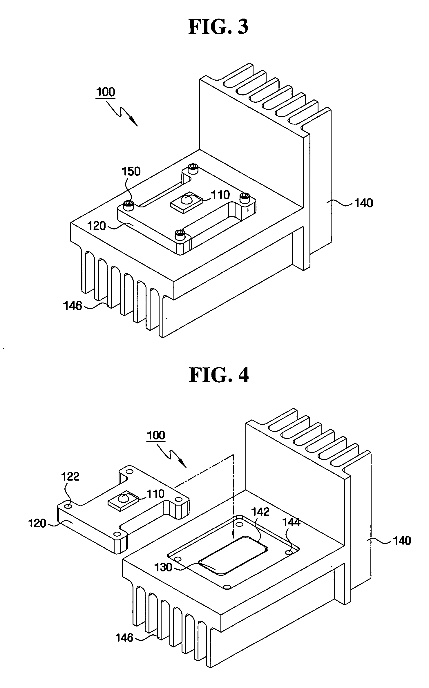
A heat-dissipating apparatus for a vehicle lamp includes: a heat-dissipating apparatus including: an LED-mounting block having an LED mounted thereon; a thermally conductive material disposed adjacent to the LED-mounting block for transmitting heat generated by the LED; and a heat sink disposed adjacent to the thermally conductive material for dissipating the heat transmitted by the thermally conductive material, wherein at least one concave portion is formed in one side of the LED-mounting block which is adjacent to the thermally conductive material, one side of the heat sink which is adjacent to the thermally conductive material, or both. The thermally conductive material is inserted in the concave portion or portions.

Description

CROSS-REFERENCE TO RELATED APPLICATION[0001]This application claims priority from Korean Patent Application No. 10-2007-0133480 filed on Dec. 18, 2007, the disclosure of which is incorporated herein by reference in its entirety.BACKGROUND[0002]1. Technical Field[0003]The present invention relates to a heat-dissipating apparatus which can position a light emitting diode (LED) more precisely.[0004]2. Related Art[0005]A vehicle is equipped with vehicle lamps. Vehicle lamps have lighting function and signaling function, among others. That is, vehicle lamps enable the driver of the vehicle to easily detect objects around and ahead of the vehicle while driving at night or in a dark area. They also inform other vehicles and road users of the vehicle's driving state. For example, a headlamp and a fog lamp are designed for the lighting function, and a direction indicator, a taillight, a brake light, and a side marker are designed for the signaling function. Typically, halogen lamps and high ...

Claims


Application Information

Patent Timeline
IPC IPC(8): F21V29/00
CPCF21S48/1159F21S48/215F21S48/328F21V29/004F21V29/89F21W2101/14F21Y2101/02F21V29/75F21V29/763F21W2101/10F21V29/67F21Y2115/10F21S41/148F21S43/14F21S45/43F21S45/48F21W2102/30F21V29/10F21V29/717F21S41/147F21S45/47F21W2102/00F21W2103/00
Inventor CHO, JIN-HWANKIM, HAK-BONG
Owner SL SEOBONG
Why Eureka
Try Eureka