Sealing a hub cavity of an exhaust casing in a turbomachine

a technology of exhaust casing and turbomachine, which is applied in the direction of machines/engines, mechanical apparatus, liquid fuel engines, etc., can solve the problems of affecting the life affecting the performance of the cylindrical jacket, and affecting the fuel consumption of the turbomachine. , to achieve the effect of simple, effective and inexpensiv

Active Publication Date: 2009-06-18
SN DETUDE & DE CONSTR DE MOTEURS DAVIATION S N E C M A
View PDF5 Cites 10 Cited by
  • Summary
  • Abstract
  • Description
  • Claims
  • Application Information

AI Technical Summary

Benefits of technology

[0008]A particular object of the invention is to provide a solution to these problems that is simple, inexpensive, and effective, enabling the drawbacks of the prior art to be avoided.

Problems solved by technology

As a result, air coming from upstream flows in the hub cavity, this air penetrating into the cavity via its upstream opening and being taken from between the high-pressure and low-pressure compressors of the turbomachine, thereby having a negative influence on the fuel consumption of the turbomachine.
This leads to a large thermal gradient in the radial arms that can harm their lifetime.
In addition, because its radial annular portion is free, the cylindrical jacket presents modes of vibration that correspond substantially to the frequencies of the rotor(s) of the turbomachine, and can thus enter into resonance with the rotor(s), thereby generating strong vibration that can harm the lifetime of the cylindrical jacket.

Method used


Image

  • Sealing a hub cavity of an exhaust casing in a turbomachine
  • Sealing a hub cavity of an exhaust casing in a turbomachine
  • Sealing a hub cavity of an exhaust casing in a turbomachine

Examples


Embodiment Construction

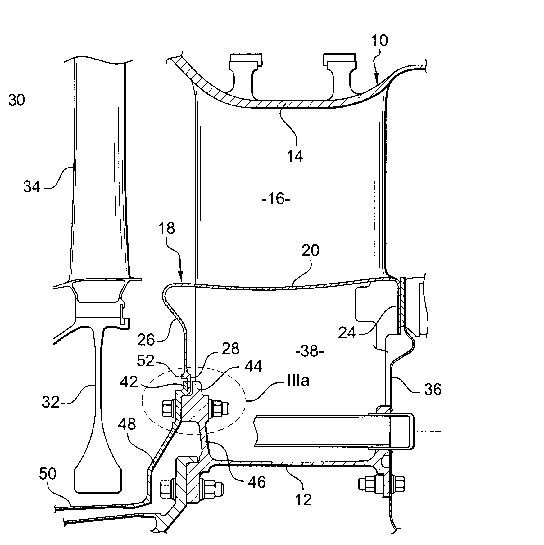
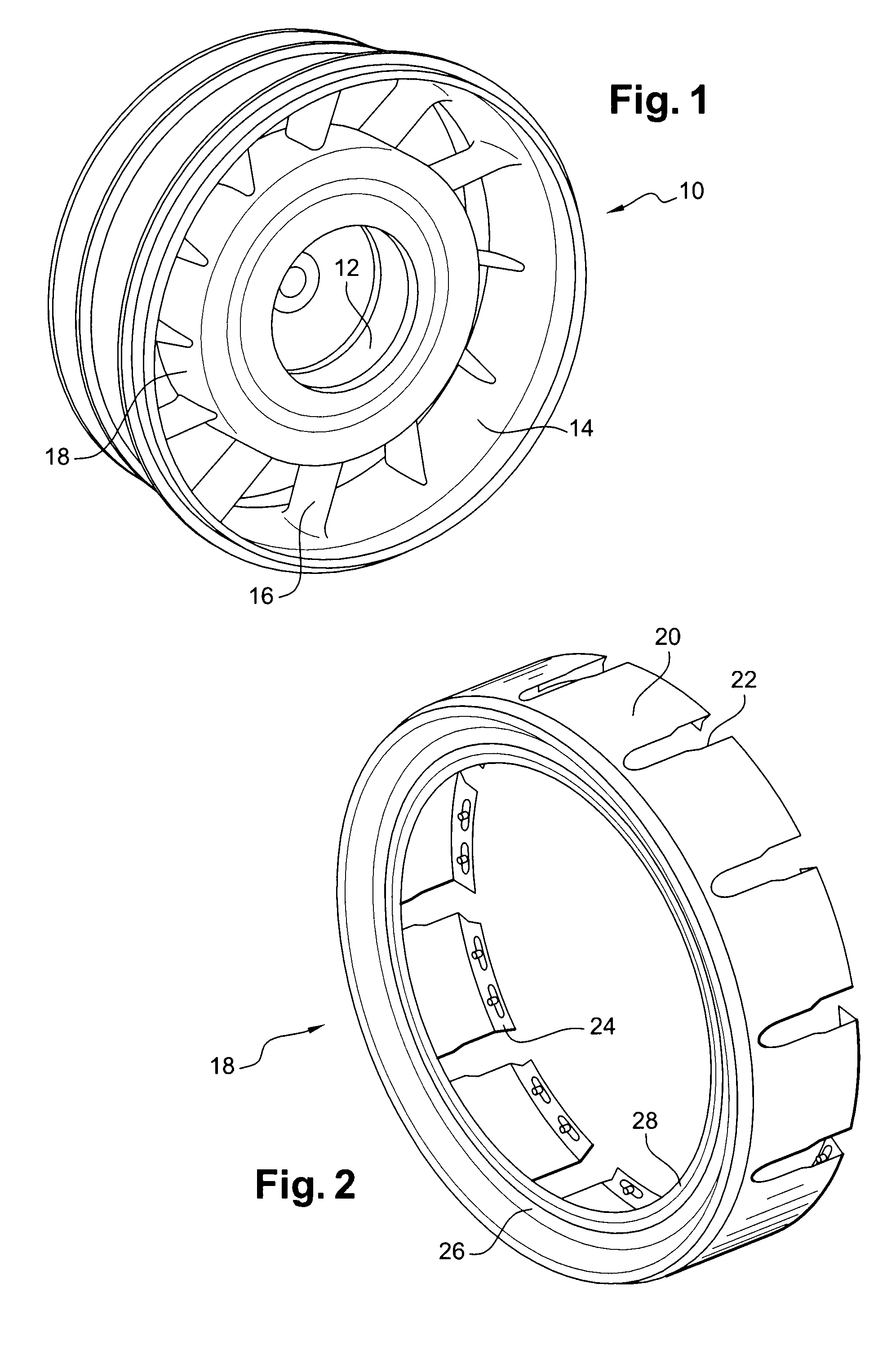
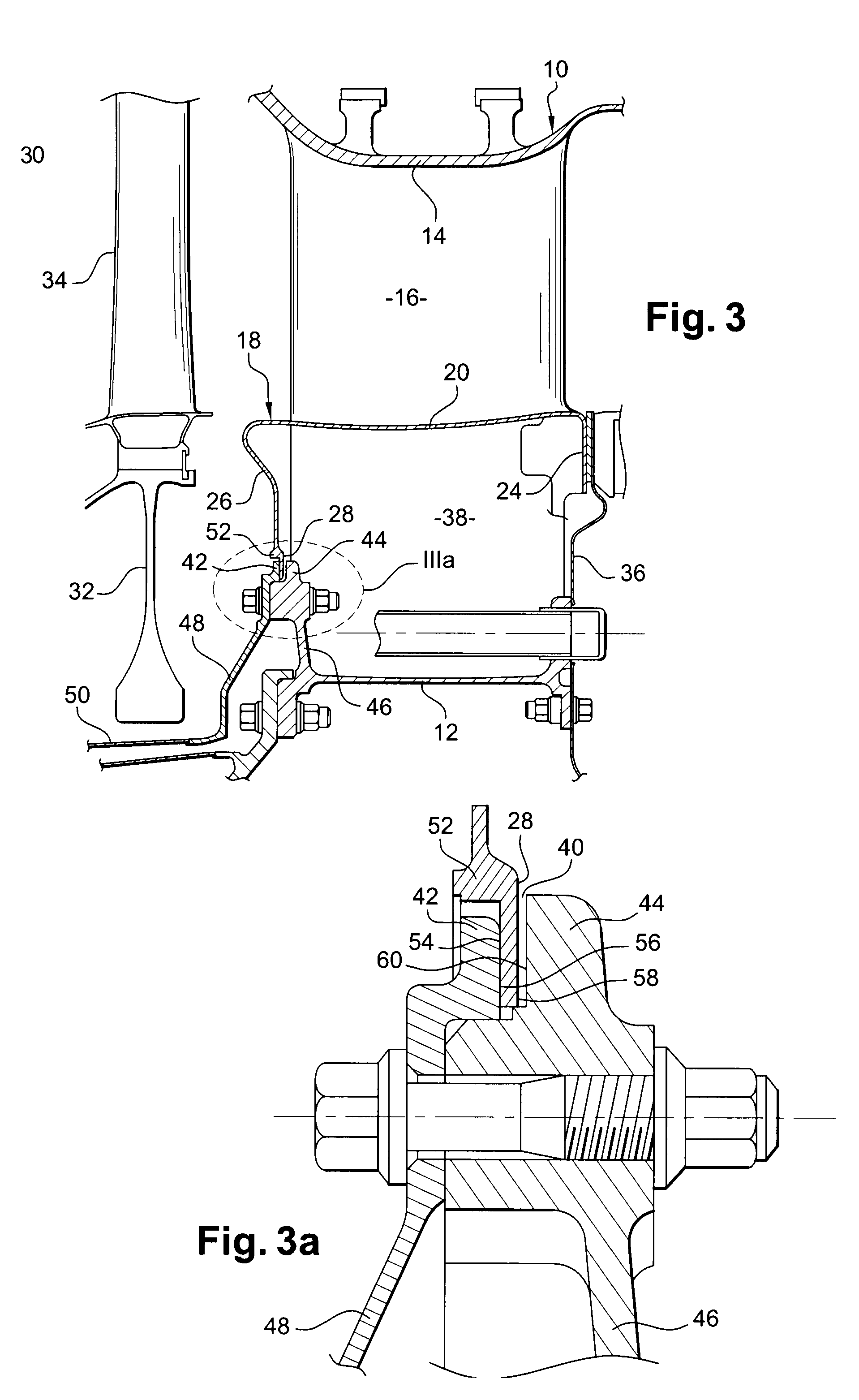
[0032]FIG. 1 shows a turbomachine exhaust casing 10 comprising two coaxial cylindrical walls, respectively a radially inner wall 12 and a radially outer wall 14, that are interconnected by structural radial arms 16.

[0033]A cylindrical jacket 18 is mounted around the radially inner wall 12 of the exhaust casing 10.

[0034]This jacket 18, shown on its own in FIG. 2, comprises a cylindrical wall 20 having cutouts 22 formed therein that are open in the downstream direction for receiving the radial arms 16 of the exhaust casing 10.

[0035]The cylindrical jacket 18 includes a radial annular flange 24 at its downstream end for fastening to the exhaust casing 10, and at its upstream end it includes a radial annular portion 26 that extends radially inwards.

[0036]As explained in greater detail below, according to the invention the jacket 18 includes an annular rim 28 formed at the radially inner end of its radial annular portion 26.

[0037]The jacket 18 and the radially outer wall 14 of the exhaust...


PUM


Abstract

The exhaust casing of a turbomachine includes a cylindrical jacket for guiding a flow of exhaust gas and for defining a hub cavity inside the casing, the jacket including at its ends an annular flange and a radial annular portion extending inwards and formed with an annular rim that is designed to be received in an annular groove of the inner wall of the exhaust casing to close the hub cavity in substantially sealed manner.

Description

[0001]The present invention relates to an exhaust casing in a turbomachine, such as an airplane turbojet, and more particularly the invention relates to sealing a hub cavity in the exhaust casing.TECHNOLOGICAL BACKGROUND OF THE INVENTION[0002]The exhaust casing of a turbomachine is mounted downstream from a turbine and generally comprises two coaxial cylindrical walls, respectively a radially inner wall and a radially outer wall, which walls are interconnected by radial arms, the inner wall being surrounded by a cylindrical jacket for guiding a flow of exhaust gas coming from the turbine.[0003]The cylindrical jacket has its downstream end fastened to the inner wall of the exhaust casing, and at its upstream end it has a radial annular portion that extends freely towards the axis of the turbomachine so that the cylindrical jacket and the inner wall of the exhaust casing together define a cavity, commonly referred to as a hub cavity.[0004]This cavity is open at the inner end of the ra...

Claims


Application Information

Patent Timeline
Patent Type & Authority Applications(United States)
IPC IPC(8): F04D29/40
CPCF01D11/005F05D2230/642F01D25/30
Inventor LESCURE, XAVIER FIRMIN CAMILLE JEANMASSOT, AURELIEN RENE-PIERREPRESTEL, SEBASTIEN JEAN LAURENTSCHNELL, CHRISTIAN RENE
Owner SN DETUDE & DE CONSTR DE MOTEURS DAVIATION S N E C M A
Why Eureka
Try Eureka