Electrical Connector

Inactive Publication Date: 2009-06-18
WONTEN TECH
View PDF15 Cites 102 Cited by
  • Summary
  • Abstract
  • Description
  • Claims
  • Application Information

AI Technical Summary

Benefits of technology

[0005]One objective of the present invention is to provide an electrical connector, in which the legs of its first terminal assembly are alternately arranged in a front/rear fashion to provide wiring with larger spacing when layout is being conducted and in tu

Problems solved by technology

However, the emerging trend in microminiaturization and complicated functioning for electrical connectors, the distance between legs is becoming so small that PCB layout is impossible.
Therefore, the layout has to be detour a

Method used


Image

  • Electrical Connector
  • Electrical Connector
  • Electrical Connector

Examples


Embodiment Construction

[0014]The structure, technical measures and effects of the present invention will now be described in more detail hereinafter with reference to the accompanying drawings that show various embodiments of the invention.

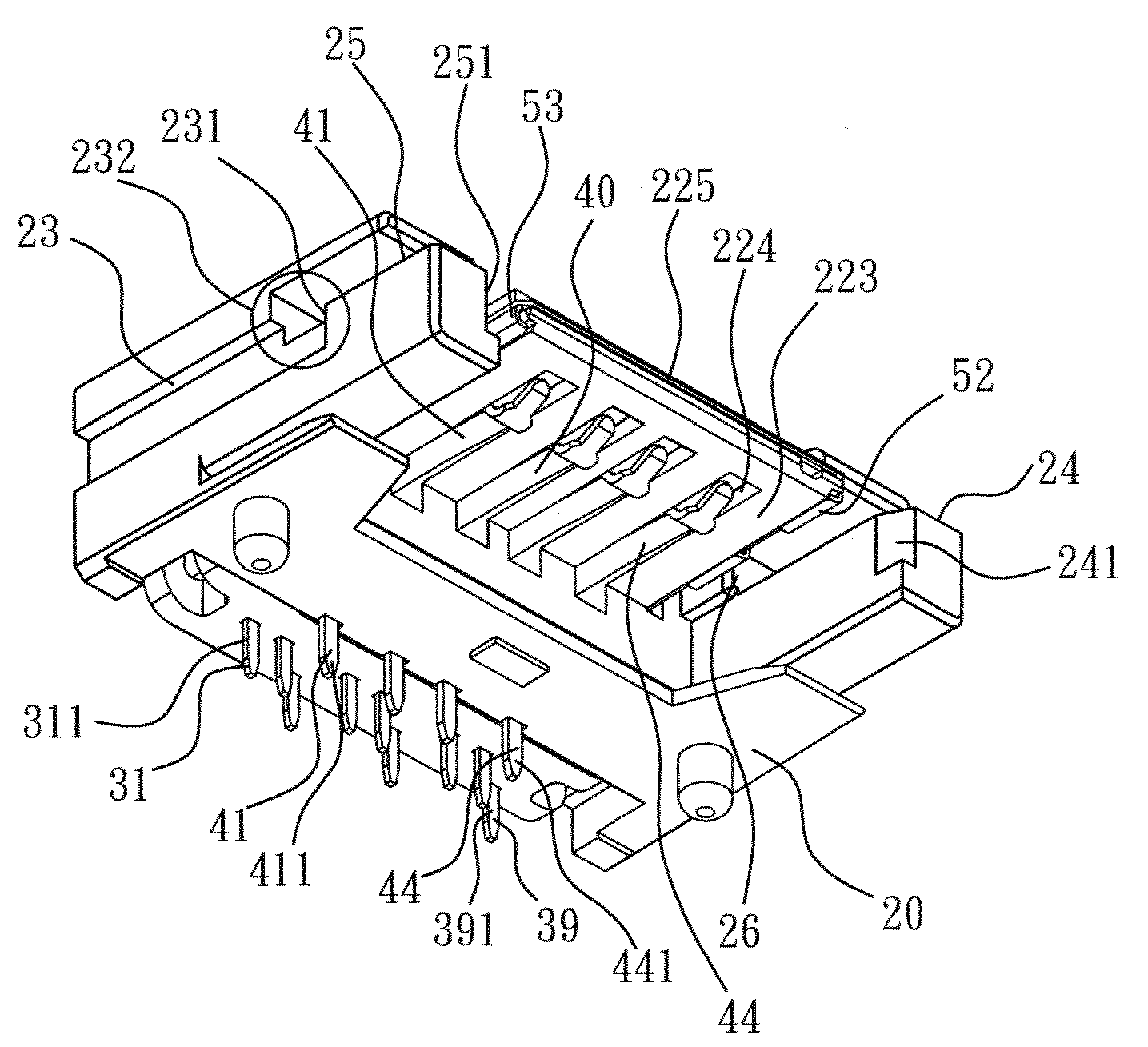
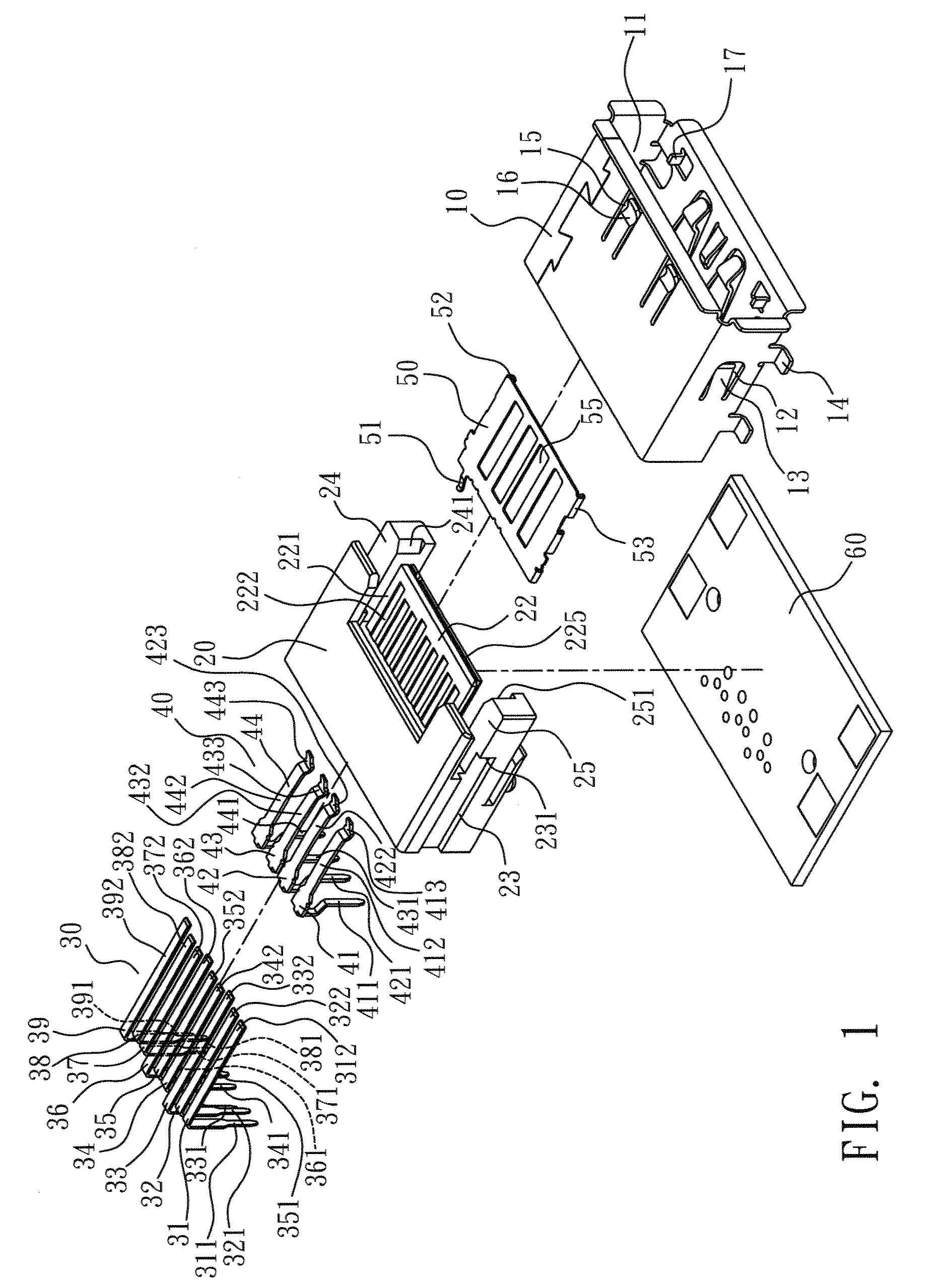
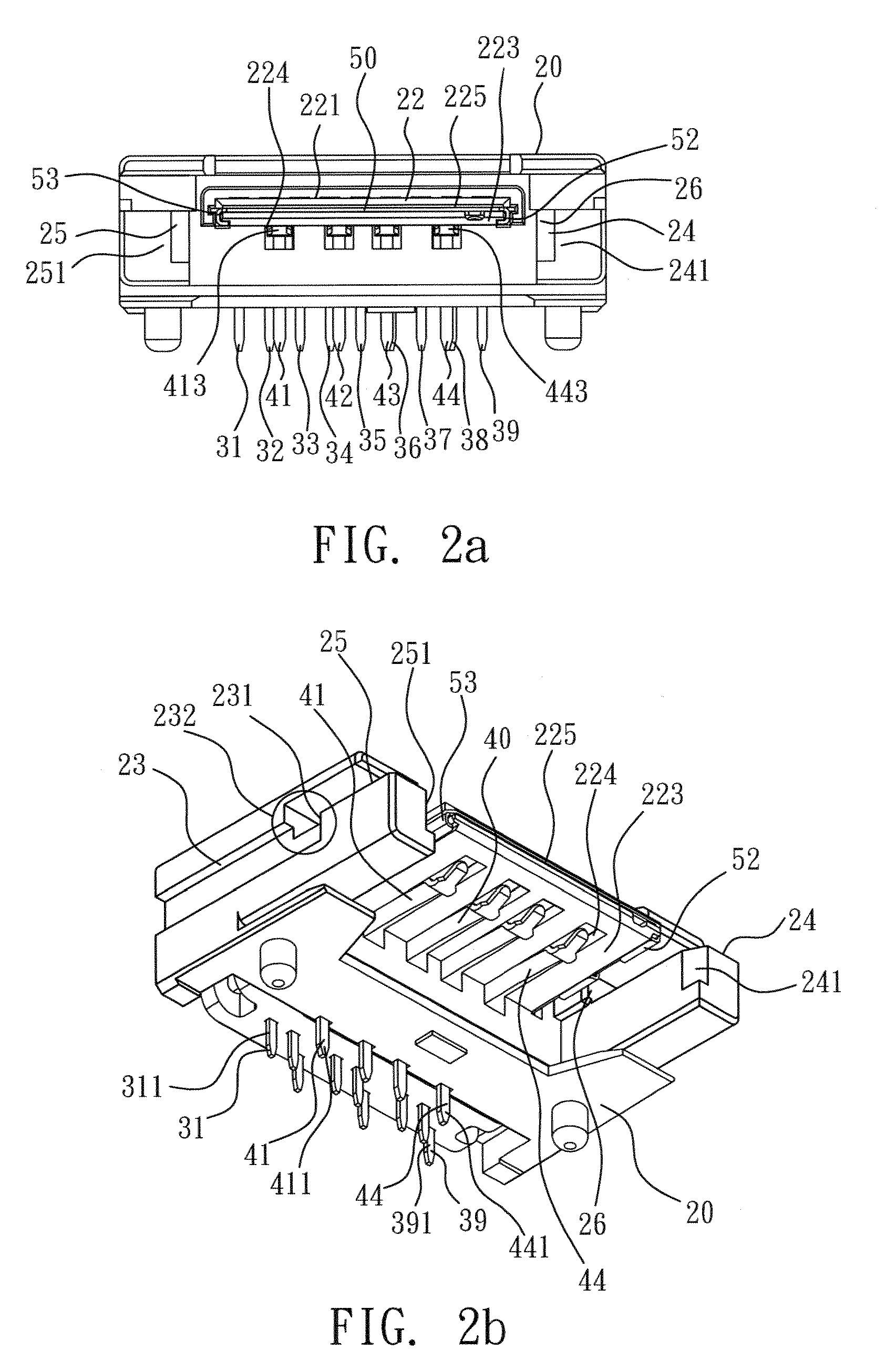
[0015]With reference to the figures, an electrical connector according to the present invention comprises, a housing 10, a base body 20, a first terminal assembly 30, and a second terminal assembly 40, wherein the housing 10 has a receiving space 11. The housing 10 is made of, for example but not limited to, metal, which is a conventional art and will not be described here furthermore. The two sidewalls of the housing 10 are formed to have a first opening 12, respectively, from which a retaining portion 13 is formed by bending inward. Also, the bottom of the two sidewalls of the housing 10 is further disposed with at least a welding piece 14 on each side, which may be further connected onto a printed circuit board 60 to enhance the retaining strength. Furthermore, the u...


PUM


Abstract

The present invention discloses an electrical connector comprising: a housing; a base body having a tongue, whose one surface is disposed with a plurality of first terminal slots and whose other surface is disposed with a plurality of second terminal slots; a first terminal assembly whose each first terminal is disposed with a leg and a contact portion slightly perpendicular to the leg, respectively, with the legs being alternately arranged; and a second terminal assembly whose each second terminal is disposed with a leg and a contact portion slightly perpendicular to the leg and then bending downward, respectively.

Description

FIELD OF THE INVENTION[0001]The present invention relates to an electrical connector, and more particularly to an electrical connector in which the legs of one of its terminal assemblies are alternately arranged in a front / rear fashion to provide wiring with larger spacing when layout is being conducted.BACKGROUND OF THE INVENTION[0002]An electrical connector; for example, but not limited to, IEEE1394, SATA, or e-SATA connector; has parallel legs so as to enable layout between legs. ROC Patent of Utility Models, 095221982, 095201553, 095201362, and 095212401, all disclose such an electrical connector.[0003]However, the emerging trend in microminiaturization and complicated functioning for electrical connectors, the distance between legs is becoming so small that PCB layout is impossible. Therefore, the layout has to be detour and thus it has become ever more complicated, and in turn the size and cost of PCB has to be increased. Thus, the drawback has significantly restricted the app...

Claims


Application Information

Patent Timeline
IPC IPC(8): H05K1/02H01R24/00H01R13/648
CPCH01R13/6485H01R12/712H01R24/62H01R13/65802H01R13/6582
Inventor CHEN, WAN-TIEN
Owner WONTEN TECH
Why Eureka
Try Eureka