
Machine for programming on-board chipsets

a chipet and programming machine technology, applied in the field of chipset programming machines, can solve the problems of reducing the utilization area and consuming a lot of time, and achieve the effect of reducing the time consumption and production cost of the code programming process

Inactive Publication Date: 2009-07-30
INVENTEC CORP
View PDF2 Cites 1 Cited by
  • Summary
  • Abstract
  • Description
  • Claims
  • Application Information

AI Technical Summary

Benefits of technology

[0007]It is therefore an aspect of the present invention to provide a machine for programming on-board chipsets, which enables users to adapt different layout designs of chipsets to program codes simultaneously into those on-board chipsets, so as to cut down in time consumption and production cost of the code programming process.
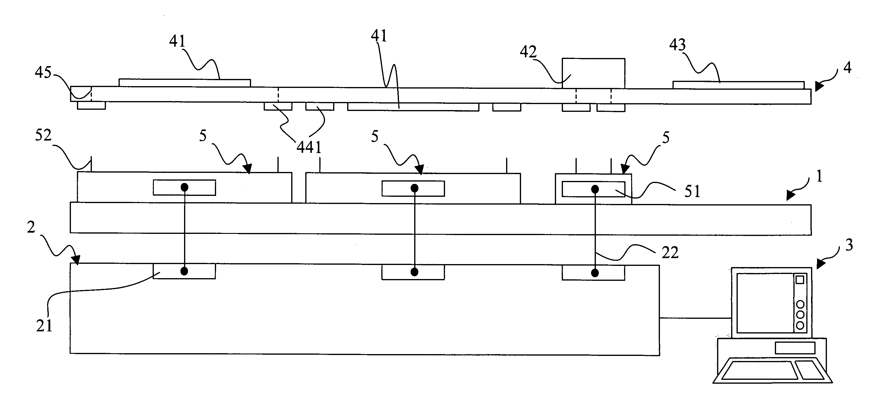
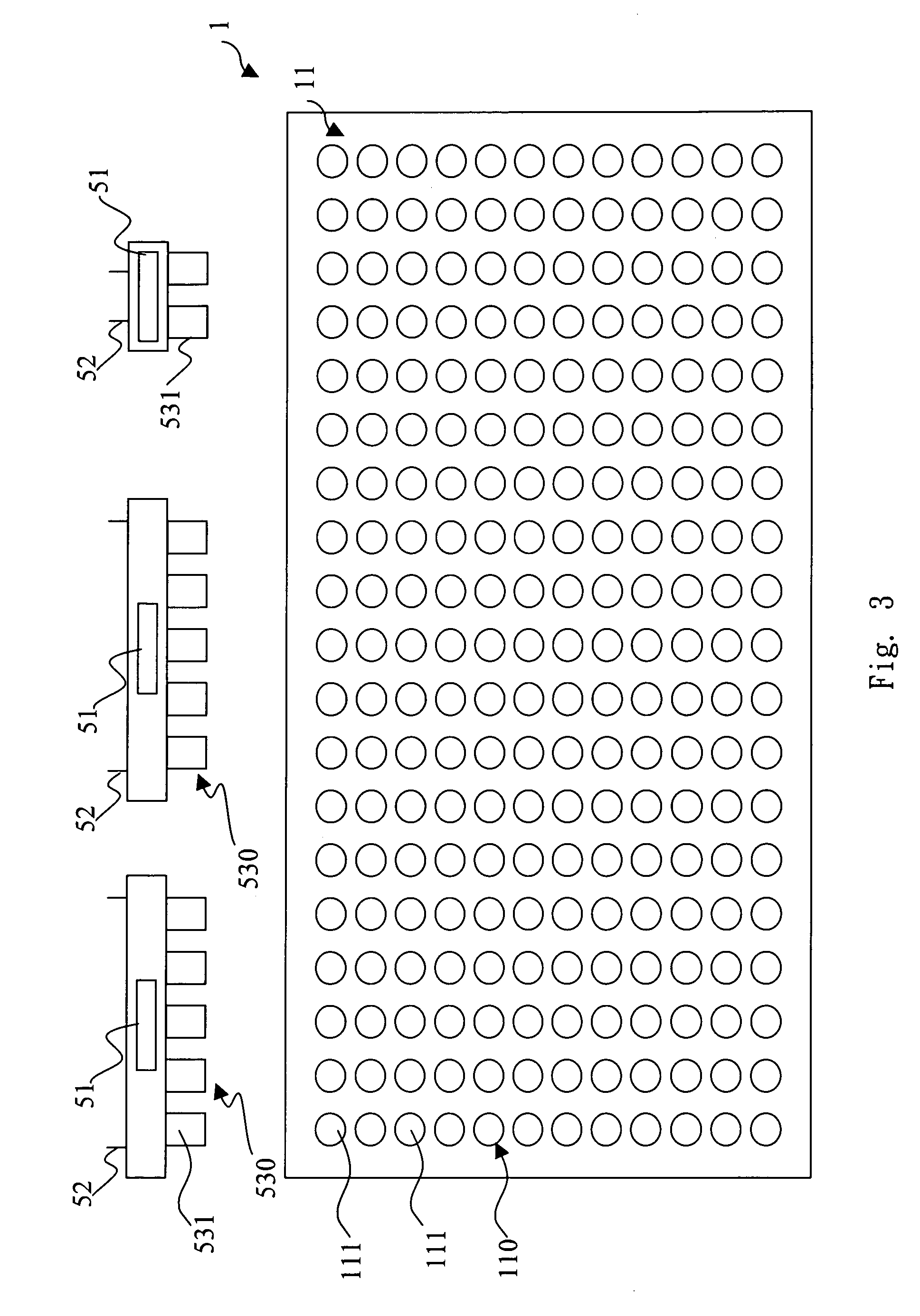
[0009]Many programming modules are electrically connected to the IC programming burner, movably disposed on the platform, and separately have a plurality of output pins extending towards the circuit board, wherein each of the output pins corresponds to one of the input pads to electrically connect the corresponding input pad when they are in contact with each other. When the output pins of one programming module are electrically connected the corresponding input pads respectively, the IC programming burner separately distributes a different set of programming codes into each chipset via the output pins and the corresponding input pads, so as to finish the code programming process of the on-board chipset.

Problems solved by technology

Therefore, in aspect of mass production, the second type of programming codes into a chipset reflects drawbacks of huge time consumption and production cost in moving the circuit board around the code programming areas, and decreasing utilized area due to the disposed code programming areas.

Method used


Image

  • Machine for programming on-board chipsets
  • Machine for programming on-board chipsets
  • Machine for programming on-board chipsets

Examples


Embodiment Construction

[0016]Reference will now be made in detail to the present preferred embodiments of the invention, examples of which are illustrated in the accompanying drawings. Wherever possible, the same reference numbers are used in the drawings and the description to refer to the same or like parts.

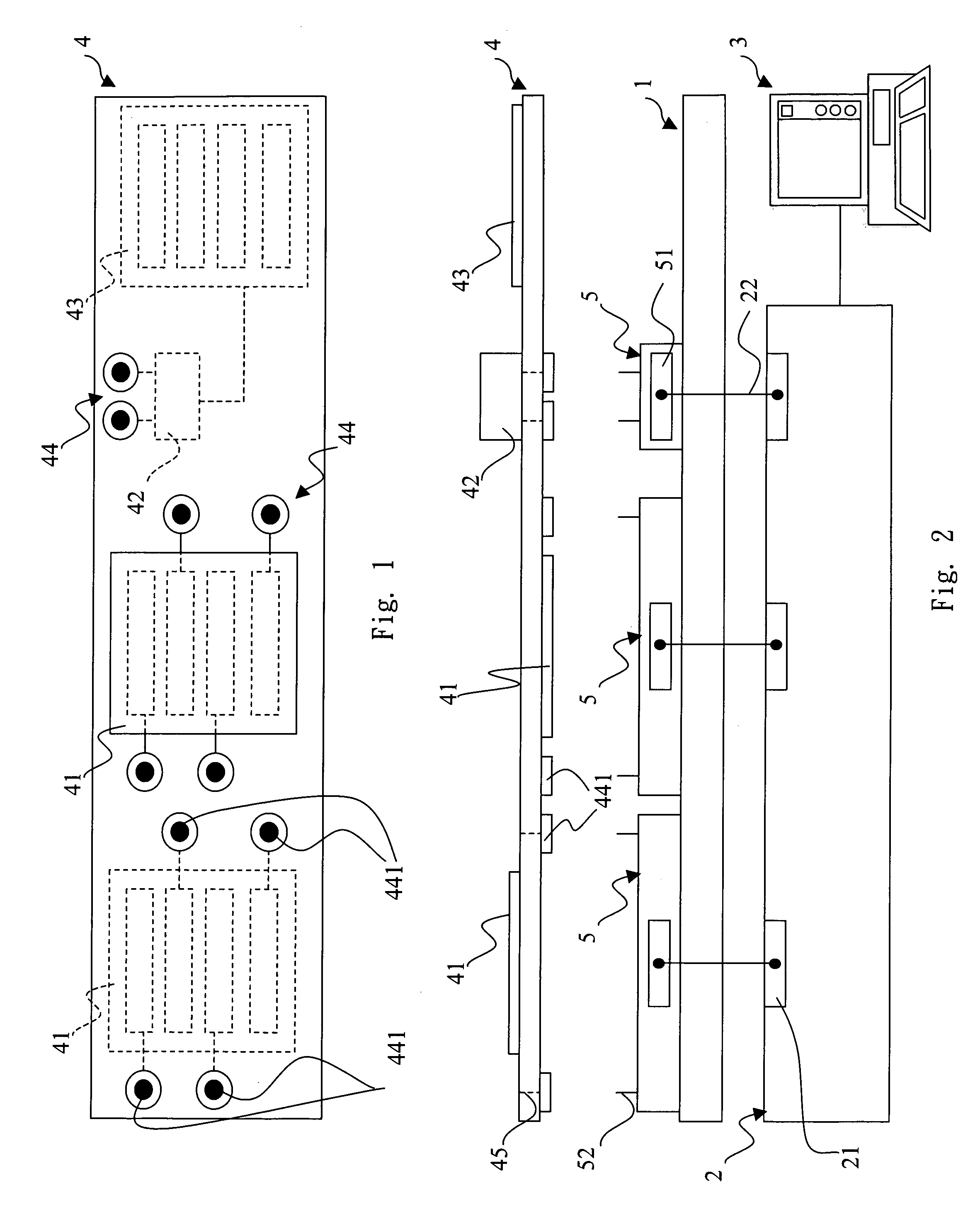
[0017]FIG. 1 is a front view of a circuit board of the present invention and FIG. 2 is a schematic diagram depicting relations to the circuit board, programming modules of a platform and an IC programming burner. A machine for programming on-board chipsets in an embodiment of the present invention comprises a platform 1, an IC programming burner 2 electrically connected to a number of programming modules 5, a computer device 3 electrically connected to the IC programming burner 2, and a circuit board 4 whose chipsets need to be programmed, has some on-board chipsets 41, at least one connecting jack 42 and a number of input portions 44 thereon. Each input portion 44 corresponds to either one chipset 4...


PUM


Abstract

The present invention discloses a machine for programming on-board chipsets, wherein the on-board chipsets means that some chipsets are mounted on a circuit board, and the circuit board has a plurality of input pads electrically connected to each chipset individually. The machine comprises a platform, a number of programming modules and an IC programming burner in which the platform faces a surface of the circuit board having the input pads, the programming modules disposed movably on the platform separately extends a number of output pins outwardly so that for connecting electrically an input pad as contacting the input pad, and the IC programming burner electrically connected to each of the programming modules separately distributes a set of programming codes into each programming module when the output pins electrically connect to the input pads.

Description

BACKGROUND[0001]1. Field of Invention[0002]The present invention relates to a machine for chipset programming. More particularly, the present invention relates to a machine for programming on-board chipsets simultaneously.[0003]2. Description of Related Art[0004]Traditionally, there are two different conditions for a chipset to save programming codes (e.g. firmware) therein. The first one is to place a chipset on an IC burner while the chipset is not mounted on the printed circuit board (PCB) yet and so that the programming codes can be directly burned-in. The second one is to save programming codes to an on-board chipset, that is, a chipset has been mounted on a PCB and the PCB may have more than one on-board chipset.[0005]Since most PCBs contain more than one on-board chipset and each on-board chipset characterizes different functions and formats, when the code programming procedure of the on-board chipsets starts, the circuit board has to be carried through different code program...

Claims


Application Information

Patent Timeline
IPC IPC(8): H03K19/173
CPCG11C16/102
Inventor CHIN, CHIH-JENTSAI, SHENG-YUAN
Owner INVENTEC CORP
Learn More