Radiator of Automobile

a technology of radiators and automobiles, applied in the direction of indirect heat exchangers, machines/engines, light and heating apparatus, etc., can solve the problems of deterioration of the output and efficiency of the electric field loading apparatus, heat transfer may occur from the radiator, and deterioration of the apparatus, so as to reduce assembly process, reduce weight and cost, and simplify the structure

Inactive Publication Date: 2010-02-25
HYUNDAI MOTOR CO LTD
View PDF10 Cites 5 Cited by
  • Summary
  • Abstract
  • Description
  • Claims
  • Application Information

AI Technical Summary

Benefits of technology

[0030]The radiator according to various aspects of the present invention can simplify the structure, cut down weight and costs, and reduce assembly process by coupling a plurality of core portions to a single header and a single tank portion.
[0031]Furthermore, by arranging the plurality of core portions in a front-rear direction, the structure is simplified and it becomes easier to secure an installation space, thus allowing the radiator according to the present invention to be applied to more cars.
[0032]Furthermore, by configuring the tank portion so as to be partitioned by a pocket or the like, heat transfer between the cooling water cooling the internal combustion engine and the cooling water cooling the electric field system is blocked, thereby improving cooling efficiency much more.

Problems solved by technology

However, the aforementioned conventional technologies have a problem that heat transfer may occur from a radiator for an engine with a high temperature to a radiator for an electric field loading apparatus because the radiator of the electric field loading apparatus and the engine radiator are integrally formed.
Owing to this, the cooling effect of the electric field loading apparatus is deteriorated, and hence the output and efficiency of the electric field loading apparatus is deteriorated due to a temperature rise of the electric field loading apparatus.
Additionally, the conventional technologies have a problem that in the case of vehicles coming with large engine displacement and vehicle weight, such as large-sized SUV and RV vehicles, it is difficult to set a high-capacity heat exchanger due to vehicle package constraints, thus making it difficult to use an integrated-type heat exchanger having a top-bottom structure (top part for an internal combustion engine and bottom part for an electric field) or a left-right structure (left side for an internal combustion engine and right side for an electric field).

Method used


Image

  • Radiator of Automobile
  • Radiator of Automobile
  • Radiator of Automobile

Examples


Embodiment Construction

[0045]Reference will now be made in detail to various embodiments of the present invention(s), examples of which are illustrated in the accompanying drawings and described below. While the invention(s) will be described in conjunction with exemplary embodiments, it will be understood that present description is not intended to limit the invention(s) to those exemplary embodiments. On the contrary, the invention(s) is / are intended to cover not only the exemplary embodiments, but also various alternatives, modifications, equivalents and other embodiments, which may be included within the spirit and scope of the invention as defined by the appended claims.

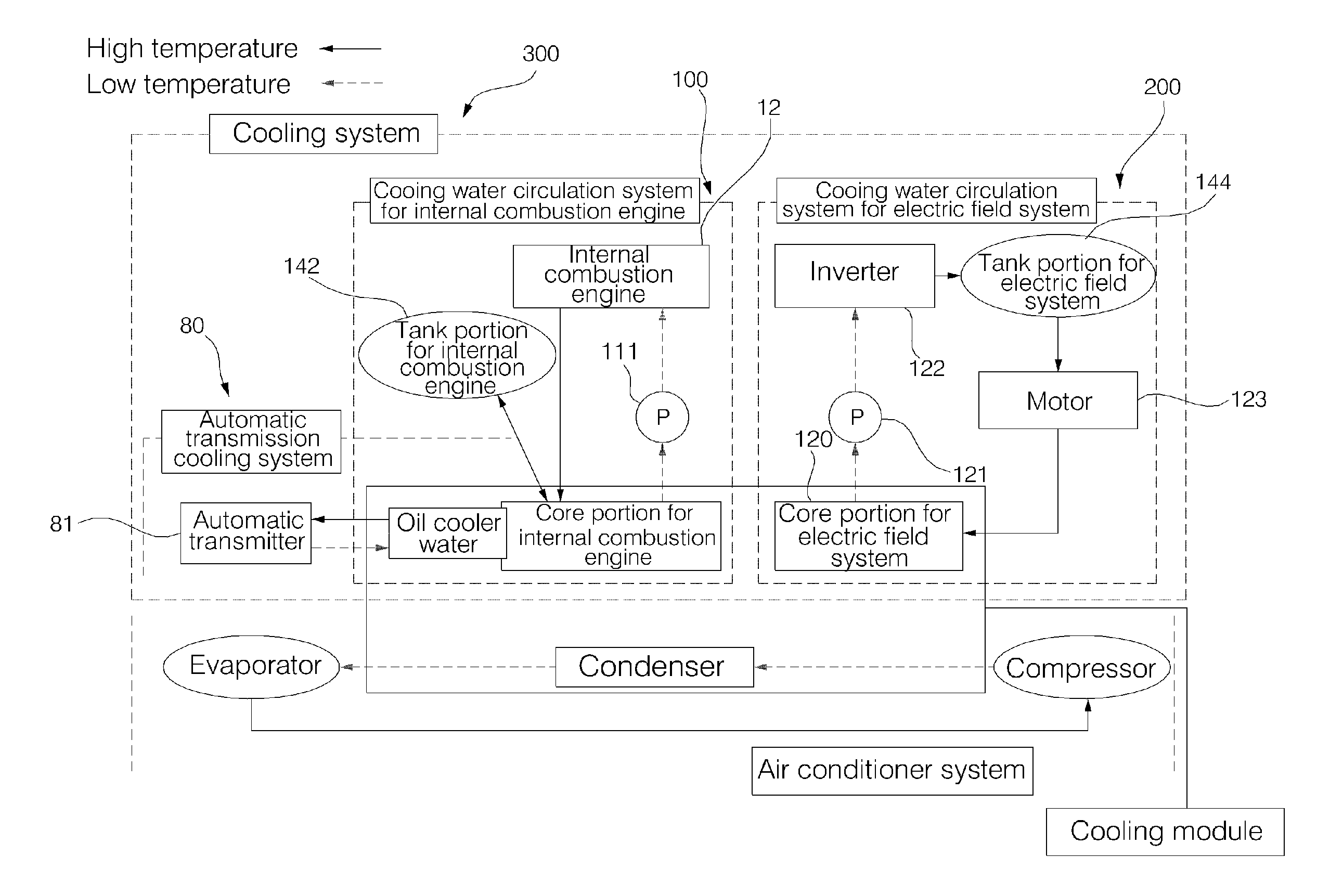
[0046]Hereinafter, a radiator of an automobile according to an exemplary embodiment of the present invention is limited to a radiator of a hybrid automobile (hereinafter, referred to as “automobile”) which combines an internal combustion engine, such as an engine, and electric field parts, such as a motor, and drive them, and will be ...


PUM


Abstract

Disclosed is a radiator which can simplify the structure, cut down weight and costs, and reduce assembly process by coupling a plurality of core portions to a single header and a single tank portion. Furthermore, by arranging the plurality of core portions in a front-rear direction, the structure is simplified and it becomes easier to secure an installation space, thus allowing the radiator according to the present invention to be applied to more cars. Furthermore, by configuring the tank portion so as to be partitioned by a pocket or the like, heat transfer between the cooling water cooling the internal combustion engine and the cooling water cooling the electric field system is blocked, thereby improving cooling efficiency much more.

Description

CROSS-REFERENCE TO RELATED APPLICATION[0001]The present application claims priority to Korean Patent Application No. 10-2008-0082461 on Aug. 22, 2008, the entire contents of which is incorporated herein for all purposes by this reference.BACKGROUND OF THE INVENTION[0002]1. Field of the Invention[0003]The present invention relates to a radiator of an automobile, and more particularly, to a cooling system which efficiently cools an internal combustion engine and an electric side in a hybrid vehicle driven by an electric motor using a battery and an internal combustion engine using fuel such as gasoline.[0004]2. Description of Related Art[0005]A hybrid vehicle is a vehicle which obtains a driving force by combining an engine and a motor and simultaneously or selectively driving them.[0006]Here, electric parts including a driving motor generate heat when activated, and there is a need to install a cooling device for suppressing a temperature rise of the parts in order to keep input / outp...

Claims


Application Information

Patent Timeline
Patent Type & Authority Applications(United States)
IPC IPC(8): F28D15/00
CPCF01P2003/185F01P2050/24F28F2009/0285F28F9/0214F28D1/0435B60H1/00B60H1/06F28D1/00
Inventor KIM, JAE YEON
Owner HYUNDAI MOTOR CO LTD
Why Eureka
Try Eureka