Non-mechanical means for connector polarization for a lighting system

a technology of non-mechanical means and connectors, applied in the field of lighting systems, can solve the problems of inefficiency and cost of manufacturing unique connectors according to the prior art, and achieve the effect of simple and inexpensive means of electrical communication

Inactive Publication Date: 2009-06-18
VARROC LIGHTING SYST SRO
View PDF13 Cites 2 Cited by
  • Summary
  • Abstract
  • Description
  • Claims
  • Application Information

AI Technical Summary

Benefits of technology

[0004]Concordant and consistent with the present invention, a non-mechanical means for connector polarization for a lighting system and a method for polarized connection, wherein the connection provides a simple and inexpensive means for electrical communication between a source of electrical energy and a light source, has surprisingly been discovered.

Problems solved by technology

Manufacturing unique connectors according to the prior art is costly and inefficient.

Method used


Image

  • Non-mechanical means for connector polarization for a lighting system
  • Non-mechanical means for connector polarization for a lighting system

Examples


Embodiment Construction

[0012]The following detailed description and appended drawings describe and illustrate various embodiments of the invention. The description and drawings serve to enable one skilled in the art to make and use the invention, and are not intended to limit the scope of the invention in any manner. In respect of the methods disclosed, the steps presented are exemplary in nature, and thus, the order of the steps is not necessary or critical.

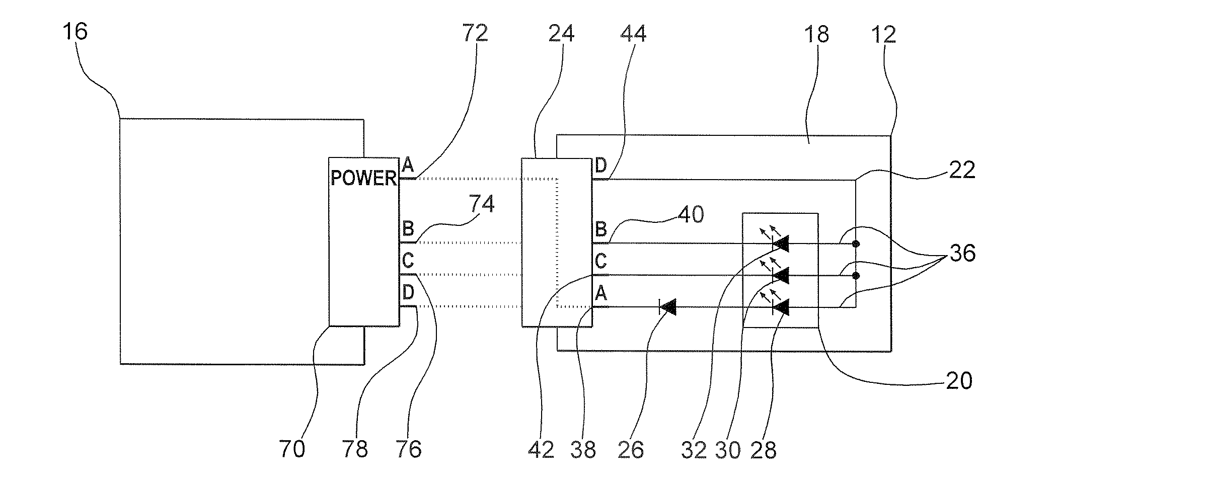
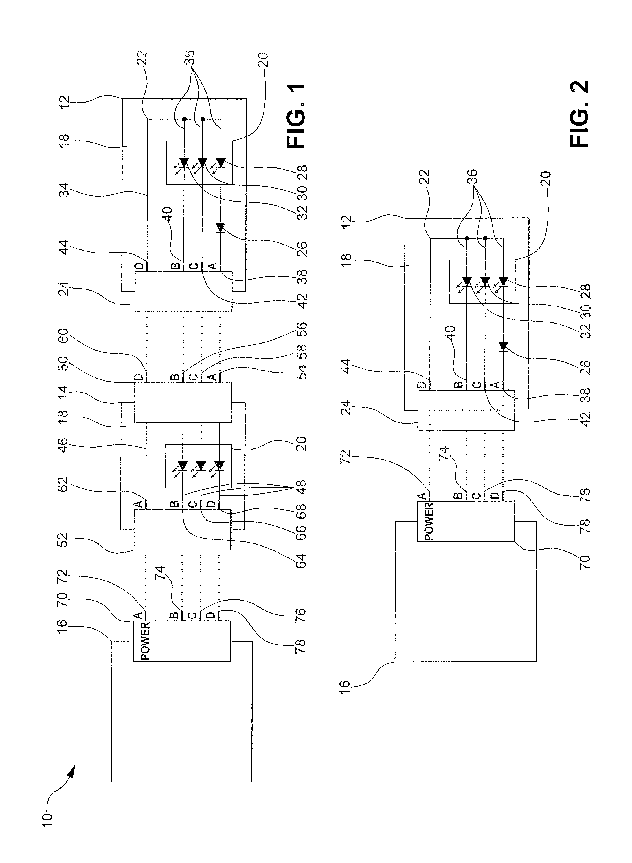
[0013]FIG. 1 illustrates a lighting system 10 according to an embodiment of the present invention. The lighting system 10 includes a first lighting module 12, a second lighting module 14, and a controller 16. It is understood that the lighting system 10 may have any number of lighting modules, as desired.

[0014]The first lighting module 12 includes a substrate 18, a light source 20, a conductive path 22, a first connector 24, and a diode 26. It is understood that the first lighting module 12 may include any conventional housing for protection such as a...


PUM


Abstract

A lighting system and method for connector polarization, wherein the lighting system includes a lighting module having a substrate, a light source disposed on the substrate, a first connector adapted to provide electrical communication with a source of electrical energy, a conductive path including a supply path and a plurality of return paths, the conductive path providing electrical communication between the light source and the connector, and a diode disposed in at least one of the return paths, wherein the diode militates against a current flowing in an undesirable direction; and a controller having a second connector adapted to provide electrical communication with the lighting module.

Description

FIELD OF THE INVENTION[0001]The present invention relates to a lighting system. More particularly, the invention is directed to a non-mechanical means for connector polarization for a lighting system.BACKGROUND OF THE INVENTION[0002]Currently, for a string of light sources with multiple break points, polarized connectors are utilized to ensure a proper connection of electrical circuits. Unique connectors are coupled at each break point in the circuit to prevent improper connection. Typically the connectors have multiple locations for a polarization rib to physically limit interconnects from occurring. Manufacturing unique connectors according to the prior art is costly and inefficient.[0003]It would be desirable to have a non-mechanical means for connector polarization for a lighting system and a method for polarized connection, wherein the connection provides a simple and inexpensive means for electrical communication between a source of electrical energy and a light source.SUMMARY...

Claims


Application Information

Patent Timeline
Patent Type & Authority Applications(United States)
IPC IPC(8): H01R13/64
CPCH05B33/0803H05B45/30
Inventor REED, DANIEL P.MIKOLAJCZAK, MATTHEW MARK
Owner VARROC LIGHTING SYST SRO
Why Eureka
Try Eureka