Catheter-to-Extension Tube Assembly and Method of Making Same

a technology of extension tubes and catheters, which is applied in the field of medical devices, can solve the problems of less-than-optimum adhesion and sealing with the polyurethane material of the hub during insert molding, and achieve the effects of less-than-optimum adhesion, less-than-optimum adhesion, and improved shape memory

Active Publication Date: 2009-06-18
MEDICAL COMPONENTS INC
View PDF13 Cites 19 Cited by
  • Summary
  • Abstract
  • Description
  • Claims
  • Application Information

AI Technical Summary

Benefits of technology

[0006]Briefly, the present invention provides a method of manufacturing a catheter assembly that includes a hub and at least one extension tube that is at least partly of silicone. A generally cylindrical fitting has a passageway therethrough, an annular collar at one end, and an at least one annular barb therearound having its angled surface facing away from the collar and a substantially perpendicular surface facing the collar. The diameter of each at least one barb is larger than the inner diameter of the passageway of the extension tube. The fitting is first inserted into a distal end of the extension tube. Preferably, an array of at least two or three annular barbs are provided on the fitting, and the angles thereof are preferably small for ease of insertion into the extension tube distal end and for minimizing the damage to the extension tube, since the fitting expands the extension tube inner diameter during insertion. The barbs will act to prevent movement of the extension tube relatively away from the fitting.
[0008]The extension tube comprises silicone and preferably a thin outer layer is provided thereover of polyurethane. The silicone has better shape memory to resist deformation by Roberts clamps and the like, and also has greater lubricity facilitating the passing therethrough of a guide wire, during insertion of the catheter into a patient, but has a disadvantage of less-than-optimum adhesion to and sealing with the polyurethane material of the hub during insert molding thereof. The thin outer layer of polyurethane provides for sealing with the molded hub, while the fitting of the present invention assures that the extension tube is firmly secured to the hub.

Problems solved by technology

The silicone has better shape memory to resist deformation by Roberts clamps and the like, and also has greater lubricity facilitating the passing therethrough of a guide wire, during insertion of the catheter into a patient, but has a disadvantage of less-than-optimum adhesion to and sealing with the polyurethane material of the hub during insert molding thereof.

Method used


Image

  • Catheter-to-Extension Tube Assembly and Method of Making Same
  • Catheter-to-Extension Tube Assembly and Method of Making Same
  • Catheter-to-Extension Tube Assembly and Method of Making Same

Examples


Embodiment Construction

[0014]In the drawings, like numerals indicate like elements throughout. Certain terminology is used herein for convenience only and is not to be taken as a limitation on the present invention. The terms “distal” and “proximal” refer, respectively, to directions closer to and away from the insertion tip of a catheter in an implantable catheter assembly. The terminology includes the words specifically mentioned, derivatives thereof and words of similar import. The embodiments illustrated below are not intended to be exhaustive or to limit the invention to the precise form disclosed. These embodiments are chosen and described to best explain the principle of the invention and its application and practical use and to enable others skilled in the art to best utilize the invention.

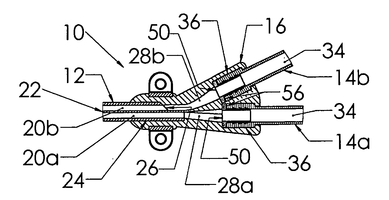
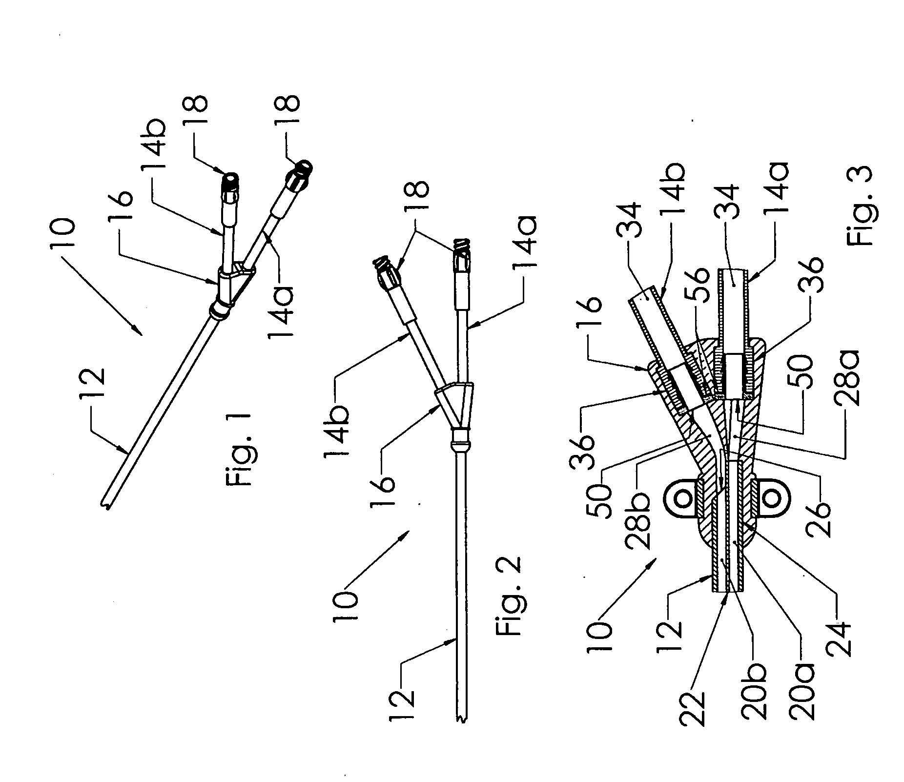
[0015]Catheter assembly 10 in FIGS. 1 and 2 includes a dual lumen catheter 12, a pair of extension tubes 14a,14b and a hub 16, with luer fittings 18 affixed to proximal ends of the extension tubes. Each extensio...


PUM

PropertyMeasurementUnit
diameteraaaaaaaaaa
inner diameteraaaaaaaaaa
movementaaaaaaaaaa

Abstract

A catheter assembly (10) having a catheter (12) with lumens (20a,20b), extension tubes (14a,14b) and a hub (16). Distal ends (36) of the extension tubes and the proximal end (24) of the catheter are secured in and to the hub. Fittings (50) are first affixed in the distal ends of the extension tubes and have annular collars (56) that are embedded in the hub when the hub is molded over the distal ends of the extension tubes during manufacturing. An array of annular barbs (60) secure the cylindrical portion (52) of each fitting in the respective extension tube distal end (36).

Description

CROSS-REFERENCE TO RELATED APPLICATIONS[0001]This application claims priority from United States Provisional Application Serial No. 61 / 007,387, filed Dec. 12, 2007.FIELD OF THE INVENTION[0002]This relates to the field of medical devices, and more particularly to catheter assemblies.BACKGROUND OF THE INVENTION[0003]Vascular catheters having extension tubes joined to their proximal ends are known, with catheters conventionally being made of either silicone or polyurethane while the extension tubes are polyurethane or polymers other than silicone. One manner of connecting an extension tube to a catheter lumen is to provide complementary luer fittings on both the proximal catheter end and the distal tube end, for removable connections. Another manner of connection, especially for use on multi-lumen catheters, is to provide a hub component that is affixed to the proximal end of the catheter and to the distal ends of one or more extension tubes associated with respective lumens of the cat...

Claims


Application Information

Patent Timeline
Patent Type & Authority Applications(United States)
IPC IPC(8): A61M25/18B29D23/00
CPCA61M25/0045A61M25/0097B29L2031/7542B29K2075/00B29C45/14467
Inventor VERBITSKY, GARYNARDEO, MAHASE
Owner MEDICAL COMPONENTS INC
Why Eureka
Try Eureka