Apparatus and method for diffusing laser energy that fails to couple into small core fibers, and for reducing coupling to the cladding of the fiber

a technology of laser energy and diffusing method, which is applied in the field of apparatus and method for diffusing laser energy that fails to couple into small core fibers, and reduces coupling to the cladding of the fiber, can solve the problems of radiant energy problem, more difficult to focus laser energy into the core, and explosively form a plume, so as to reduce the coupling of higher-order modes

Inactive Publication Date: 2006-08-15
BROWN JOE D
View PDF30 Cites 55 Cited by
  • Summary
  • Abstract
  • Description
  • Claims
  • Application Information

AI Technical Summary

Benefits of technology

[0023]It is accordingly a first objective of the invention to provide an apparatus and method for coupling a laser to an optical fiber or other primary optical transmission system, in which energy that does not couple to the primary optical transmission system is diffused to prevent damage to components of the coupling connector, and which therefore extends the useful life of the connector, ensures efficient coupling of a portion of the radiant energy to the transmission system, enables the use of smaller transmission components, for example fibers with smaller diameters and / or acceptance angles, and that accommodates greater tolerances in aligning the transmission system to the radiant energy source, without the need for internal reflectors.
[0024]It is a second objective of the invention to provide an improved method of coupling a laser to an optical fiber in a way that facilitates use of relatively small optical fibers while minimizing damage to the coupling connector and components thereof, and yet that is compatible with standard laser coupling connectors, including medical laser industry standard metal connectors, and that does not require any external heat sinks that would interfere with such compatibility.
[0025]It is a third objective of the invention to provide an improved method of coupling a laser to an optical fiber in a way that facilitates use of relatively small optical fibers while minimizing damage to the coupling connector and components thereof, and yet that is compatible with standard laser coupling connectors, including medical laser industry standard metal connectors.
[0026]It is a fourth objective of the invention to provide an arrangement for coupling a laser to an optical fiber in a way that reduces or eliminates coupling to the cladding rather than the core.
[0027]It is a fifth objective of the invention to provide an apparatus and method for coupling a laser or other radiant energy source to an optical fiber or other primary optical transmission system, which has the effect of reducing higher order radiant energy modes.
[0028]These objectives are achieved, in accordance with the principles of a preferred embodiment of the invention, by a connector in which the optical fiber is surrounded by at least one diffuser for diffusing the radiant energy rather than simply converting it to heat and dissipating it in a heat sink. By diffusing the radiant energy in this manner, the preferred embodiment minimizes damage to the connector while in a simple, low cost manner that enables the connector to be manufactured to existing specifications, for use in existing laser devices without modification of the devices.

Problems solved by technology

The errant radiant energy problem arises when the primary optical transmission system approaches or is smaller than the size of the focused beam of radiant energy.
For example, the smaller the diameter of an optical fiber, the more difficult it is to focus energy from the laser into the core.
In many cases the energy density can be so great that photo thermal ablation may occur in the metal housing of the connector that couples the laser to the fiber, causing the metal to explosively form a plume mixture gases and micron size particles, which re-deposit and contaminate the focusing lens.
Further lasing into the contamination can create extreme localized heating which ultimately destroys the focusing lens.
The arrangement disclosed in U.S. Pat. No. 5,179,610 can, in theory, effectively divert radiation away from components of the fiber optic termination or connector, but implementation of the arrangement requires replacement of the conventional supporting structure, making it difficult to adapt the arrangement to existing fiber terminations.
As a result, the arrangement disclosed in U.S. Pat. No. 5,179,610 does not appear to be compatible with existing laser systems and connectors, and in particular does not appear to be well-adapted for use with standard medical laser industry connectors, such as the SMA 905 standard connector.
Damage to the cladding or coating will occur if these surfaces are unable to withstand the incident power or energy density.
Continued damage to these surfaces can ultimately lead to total destruction or breakage of the overall fiber.
Since higher order radiation modes are by definition modes in which the angle of incidence is relatively high, higher order modes are more likely to exceed the critical angle at a bend in the fiber, and therefore leak to the cladding.
However, both solutions are undesirable for many applications.
Larger N.A.s are limited, due to choices of fiber core / clad materials versus transmission at a particular wavelength.
Therefore, choices of larger N.A. fibers are limited in many state of the art minimally-invasive surgical techniques involving, for example, scalpels or lithotripter fibers, while decreasing the numerical aperture of the radiation source is often impractical due to the already large installed base of lasers, theoretical limitations and FDA regulations on making modifications to existing lasers.

Method used


Image

  • Apparatus and method for diffusing laser energy that fails to couple into small core fibers, and for reducing coupling to the cladding of the fiber
  • Apparatus and method for diffusing laser energy that fails to couple into small core fibers, and for reducing coupling to the cladding of the fiber
  • Apparatus and method for diffusing laser energy that fails to couple into small core fibers, and for reducing coupling to the cladding of the fiber

Examples


Embodiment Construction

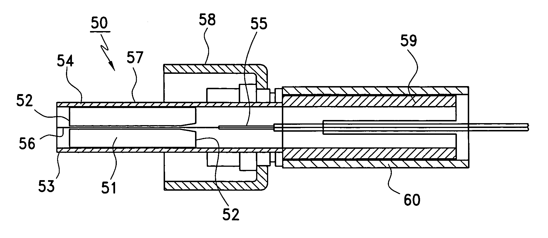
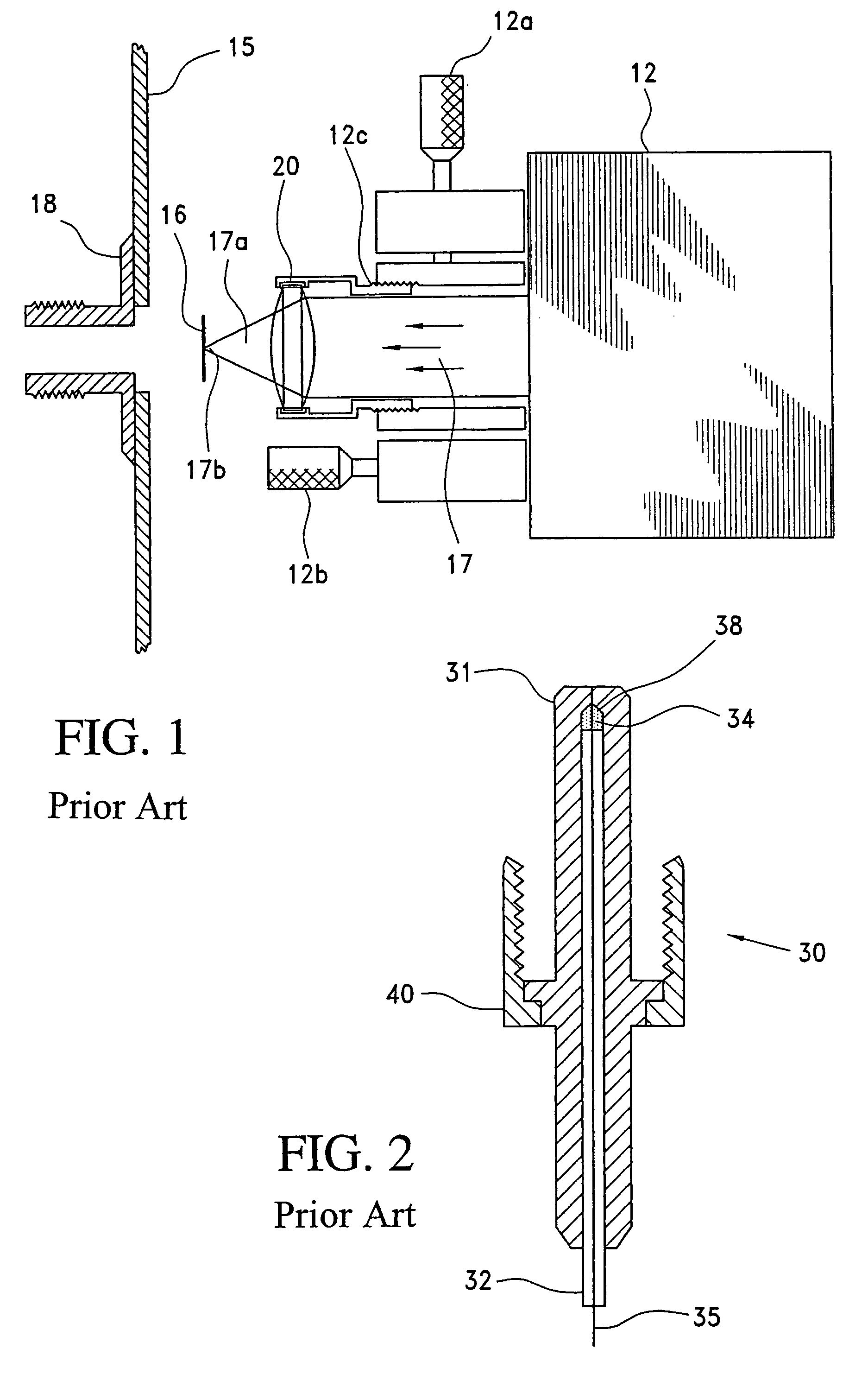
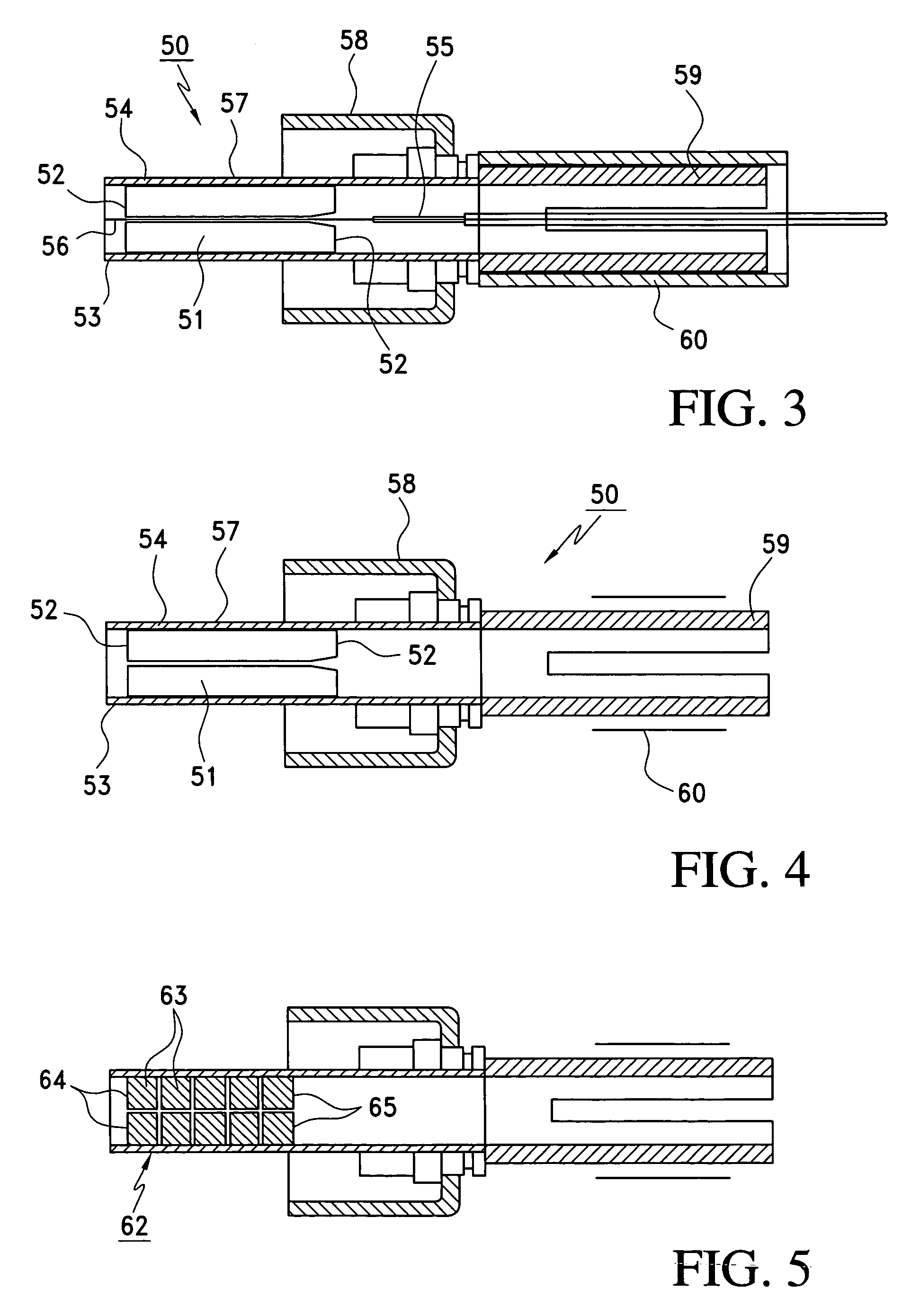
[0043]FIGS. 3 and 4 illustrate a connector constructed in accordance with the principles of a preferred embodiment of the invention, for coupling to a coupling connector corresponding to coupling connector 18 illustrated in FIG. 1. It will of course be appreciated by those skilled in the art that the principles of the invention may be applied to laser apparatus other than the apparatus illustrated in FIG. 1, and that the invention is not intended to be limited to a particular laser source or connector coupling arrangement.

[0044]Turning to FIGS. 3 and 4, connector 50 is identical in size to connector 30 of FIG. 2, but differs in that the connector includes a transparent cylindrical alignment ferrule 51 having diffusers 52 at opposite ends. The diffusers are in the form of roughened surfaces of the ferrule 51, and in particular in the form of surfaces having a rough polish, although roughening may of course be achieved by means other than polishing, such as chemical or laser etching, ...


PUM


Abstract

A fiber optic connector for coupling focused radiant energy from a laser to a fiber optic conductor includes a secondary transmission path, one or more diffusers and, optionally, one or more internal heat sinks for diffusing radiant energy so as to and thereby minimize damage to the connector. In addition, coupling of the radiant energy to the cladding of the fiber is minimized by stripping or at least partially removing the cladding to reduce the amount of cladding in the area that extends to the focal plane of the radiant energy source, while reduction of higher order propagation modes may optionally be achieved by tapering a section of the fiber in such a manner that light entering the fiber at large critical angles are effectively collimated, i.e., bent towards the axis of the fiber.

Description

[0001]This application claims the benefit of U.S. Provisional Application Ser. No. 60 / 507,106, filed Oct. 1, 2003, and 60 / 482,455, filed Jun. 26, 2003. U.S. Provisional Application Ser. No. 60 / 482,455 is a continuation-in-part of U.S. patent application Ser. No. 10 / 370,453, filed Feb. 24, 2003, which claims the benefit of provisional U.S. Patent Application Ser. No. 60 / 358,309, filed Feb. 24, 2002, and which is herein incorporated by reference.BACKGROUND OF THE INVENTION[0002]1. Field of the Invention[0003]This invention relates to improvements over the system disclosed in U.S. Pat. No. 5,179,610, in which radiation that fails to couple,with a small core fiber is transmitted via a secondary transmission path to a “dissipation chamber,” a reflector, and an external heat sink that converts the reflected radiation to heat.[0004]The first improvement is to use diffusion to spread-out the errant radiation, thereby minimizing damage caused by the radiation and eliminating the need for a r...

Claims


Application Information

Patent Timeline
Patent Type & Authority Patents(United States)
IPC IPC(8): G02B6/42A61B18/22
CPCG02B6/4296G02B6/4292
Inventor BROWN, JOE D.
Owner BROWN JOE D
Why Eureka
Try Eureka