Controller for a Hydraulically Operated Downhole Tool

Active Publication Date: 2009-06-25
BAKER HUGHES INC
View PDF14 Cites 27 Cited by
  • Summary
  • Abstract
  • Description
  • Claims
  • Application Information

AI Technical Summary

Benefits of technology

[0013]A hydraulic control system can be used on a downhole choke and has the feature of moving a travel stop for a sliding sleeve using discrete j-slot mechanisms for selectively moving the stop in either one of two opposed directions. The valve can be incrementally opened further with pressure cycling on an opening chamber. The valve can be immediately put to the closed position with pressure

Problems solved by technology

This design does not allow the valve to always be closed with a single comman

Method used


Image

  • Controller for a Hydraulically Operated Downhole Tool
  • Controller for a Hydraulically Operated Downhole Tool
  • Controller for a Hydraulically Operated Downhole Tool

Examples


Embodiment Construction

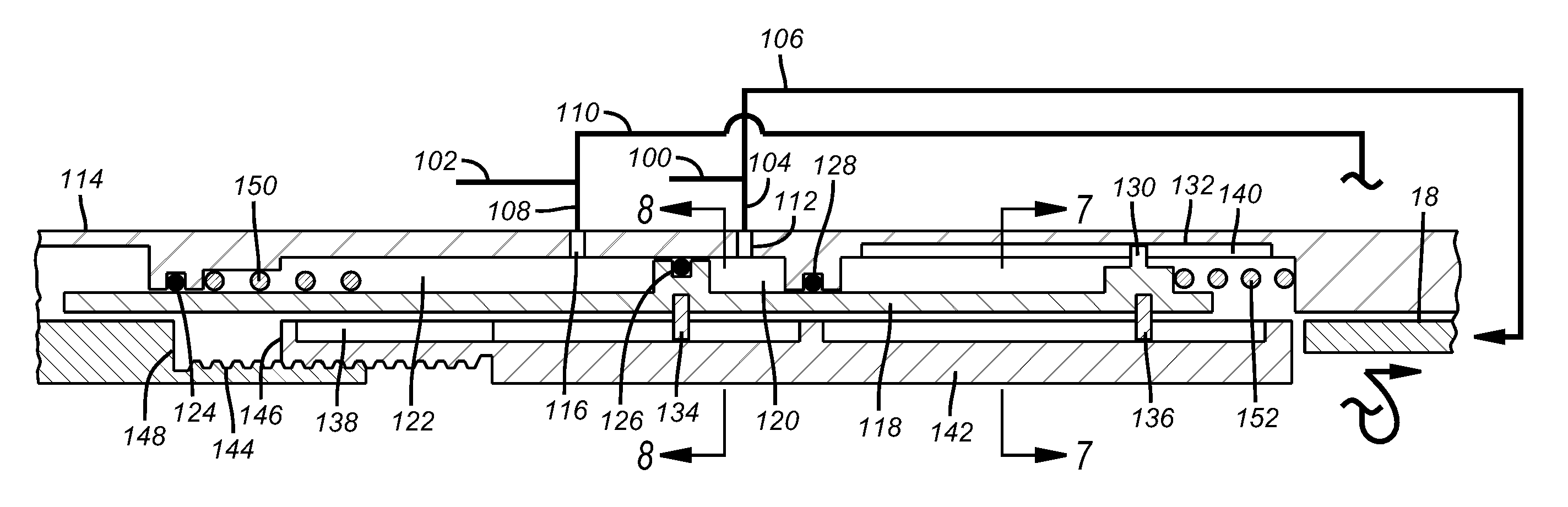
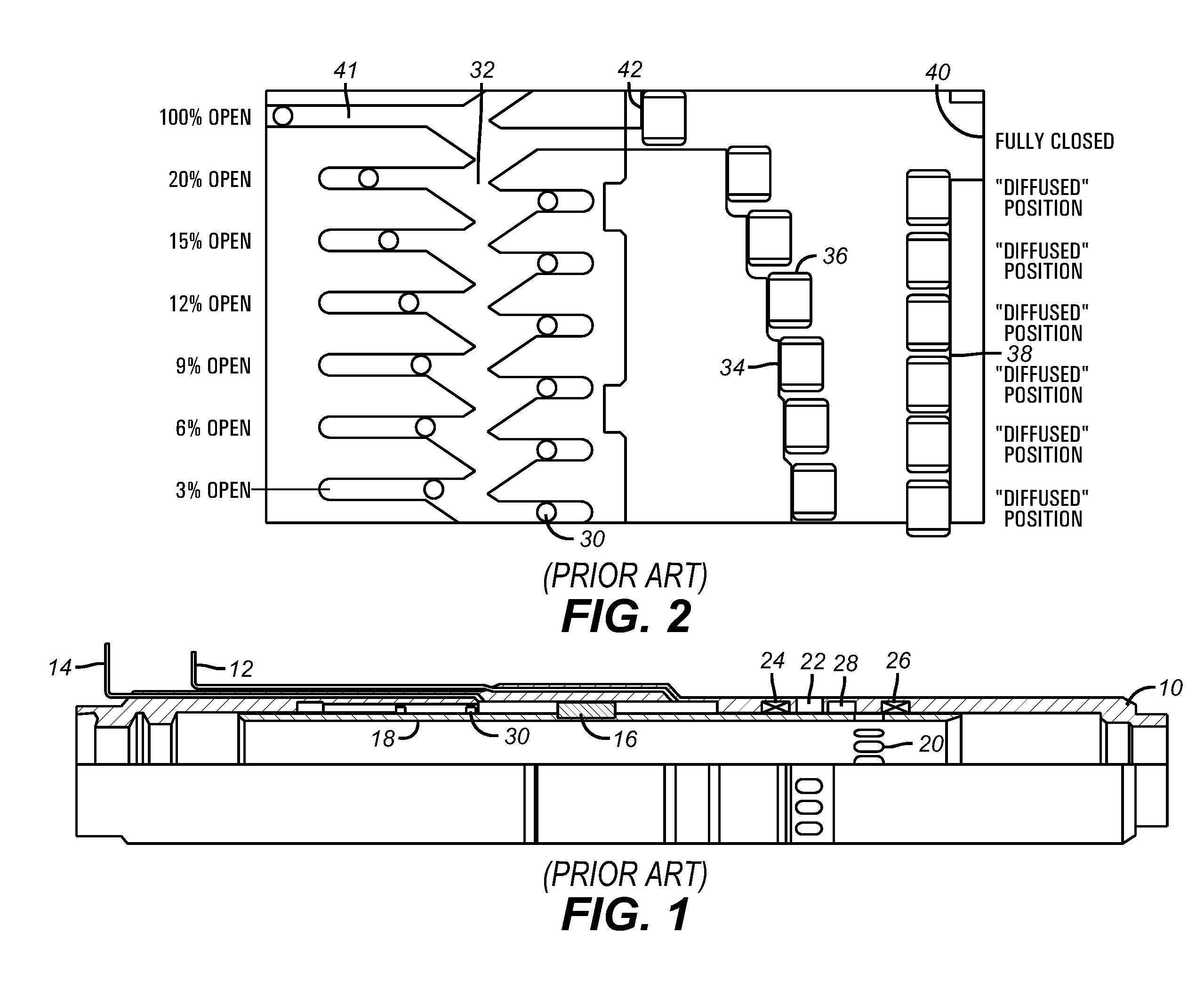
[0028]For continuity, FIG. 6 shows the insert sleeve 18, for the valve in FIG. 1. The present invention is focused on the control system and one application is on a valve with a basic structure as shown in FIG. 1 although uses on other downhole tools are envisioned. There are two control lines 100 and 102 that extend from the surface. Line 100 branches into lines 104 and 106 and line 102 branches into lines 108 and 110. Line 104 goes into opening port 112 in body 114. Line 108 goes to closing port 116 in body 114. A piston 118 defines opening chamber 120 and closing chamber 122 between itself and body 114 with the aid of seals 124, 126 and 128. Piston 118 has a key 130 that rides in track 132 in the body 114 to limit the movement of piston 118 to longitudinal only without relative rotation. Piston 118 supports upper j-slot pin 134 and lower j-slot pin 136. Pin 134 can selectively enter and exit j-slot assembly 138 on travel stop 142 for rotation of travel stop 142 in a manner so as ...


PUM


Abstract

A hydraulic control system can be used on a downhole choke and has the feature of moving a travel stop for a sliding sleeve using discrete j-slot mechanisms for selectively moving the stop in either one of two opposed directions. The valve can be incrementally opened further with pressure cycling on an opening chamber. The valve can be immediately put to the closed position with pressure on a closing chamber. After closing, the valve can assume its former open position or other selected less open positions by reconfiguring the travel stop while the valve stays in the closed position In order to achieve a higher open percent after closing, one or more pressure cycles must be applied to the open chamber after the valve is reopened to the position it was in before it was closed.

Description

FIELD OF THE INVENTION[0001]The field of the invention is control systems for hydraulically operated downhole tools and more particularly sliding sleeve valves that operate in multiple positions including fully open and closed.BACKGROUND OF THE INVENTION[0002]Flow during production is regulated by a valve called a choke. The typical design for a choke comprises a body having a series of lateral ports and a sliding sleeve that has a matching port layout. A hydraulic system is used to move the insert sleeve in opposed directions. The hydraulic system also controlled the movement of the insert sleeve broadly in two different ways, both of which will be described in detail below.[0003]In the J-slot design cycles of pressure application and removal made a pin follow a j-slot. A lug also on the movable member with the pin followed the pattern defined by the j-slot and with each cycle of application and removal of pressure the lug would encounter a different fixed travel stop that would de...

Claims


Application Information

Patent Timeline
IPC IPC(8): E21B34/00
CPCE21B23/006E21B2034/007E21B34/10E21B2200/06
Inventor LAUDERDALE, DONALD P.
Owner BAKER HUGHES INC
Why Eureka
Try Eureka