

Constant work tool angle control
a constant angle and work tool technology, applied in the direction of program control, thinning machines, instruments, etc., can solve the problems of uneven ground along the ditch, high-skilled operators cannot perform a ditch clearing operation as quickly, and cannot vary the angle of work tools based on the task the machine is performing
- Summary
- Abstract
- Description
- Claims
- Application Information
AI Technical Summary
Problems solved by technology
Method used
Image

Examples
Embodiment Construction
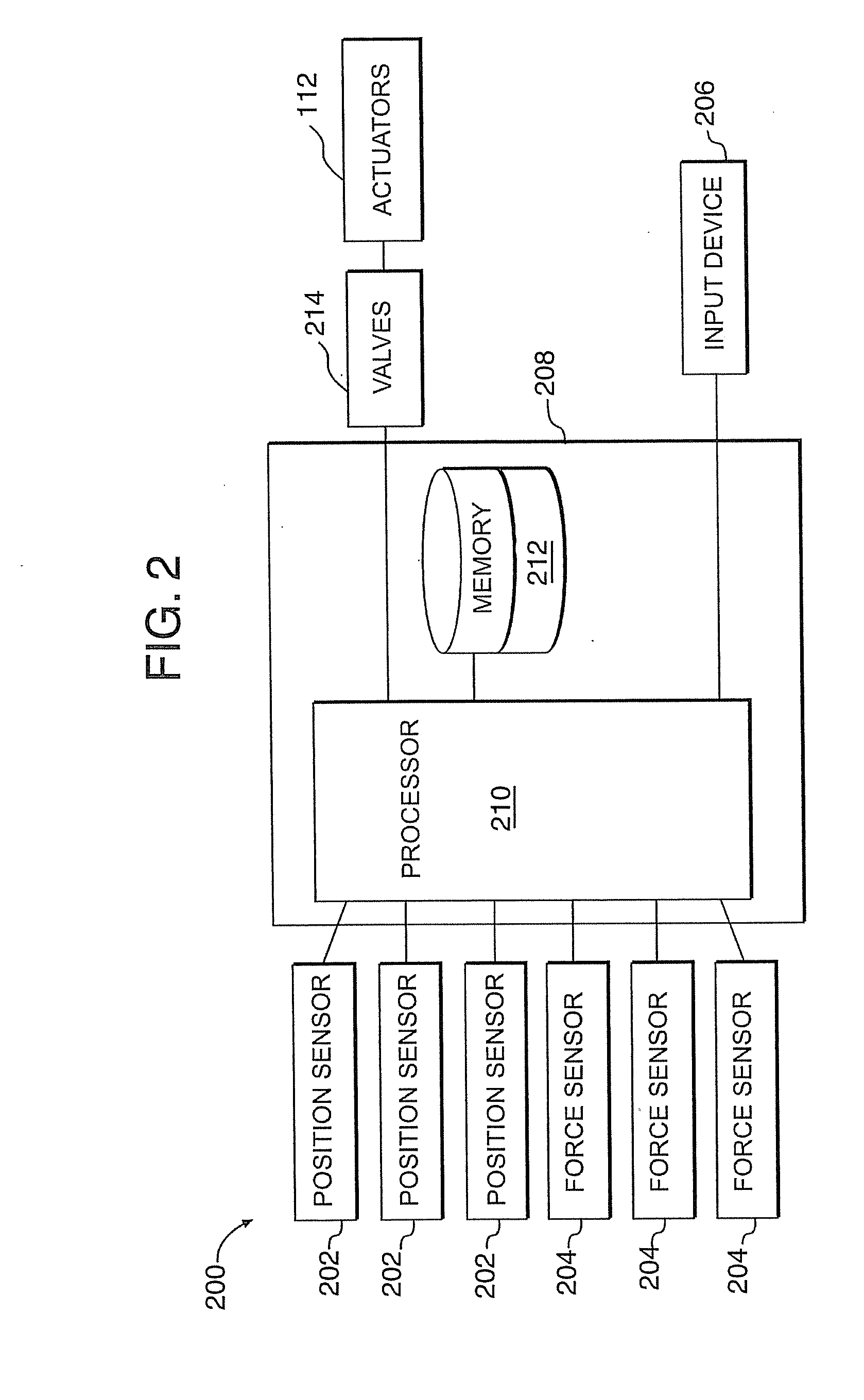
[0015]This disclosure relates to a system and method for controlling a work tool connected to a machine. The described technique includes identifying a design surface gradient either automatically or manually, determining an angle for the work, monitoring the movement of the machine, determining a distance from the design surface gradient to the work tool and finally varying the angle of the work tool, such that the angle of the work tool is based on the current angle of the work tool, the movement of the machine and the distance from the design surface gradient to the work tool.
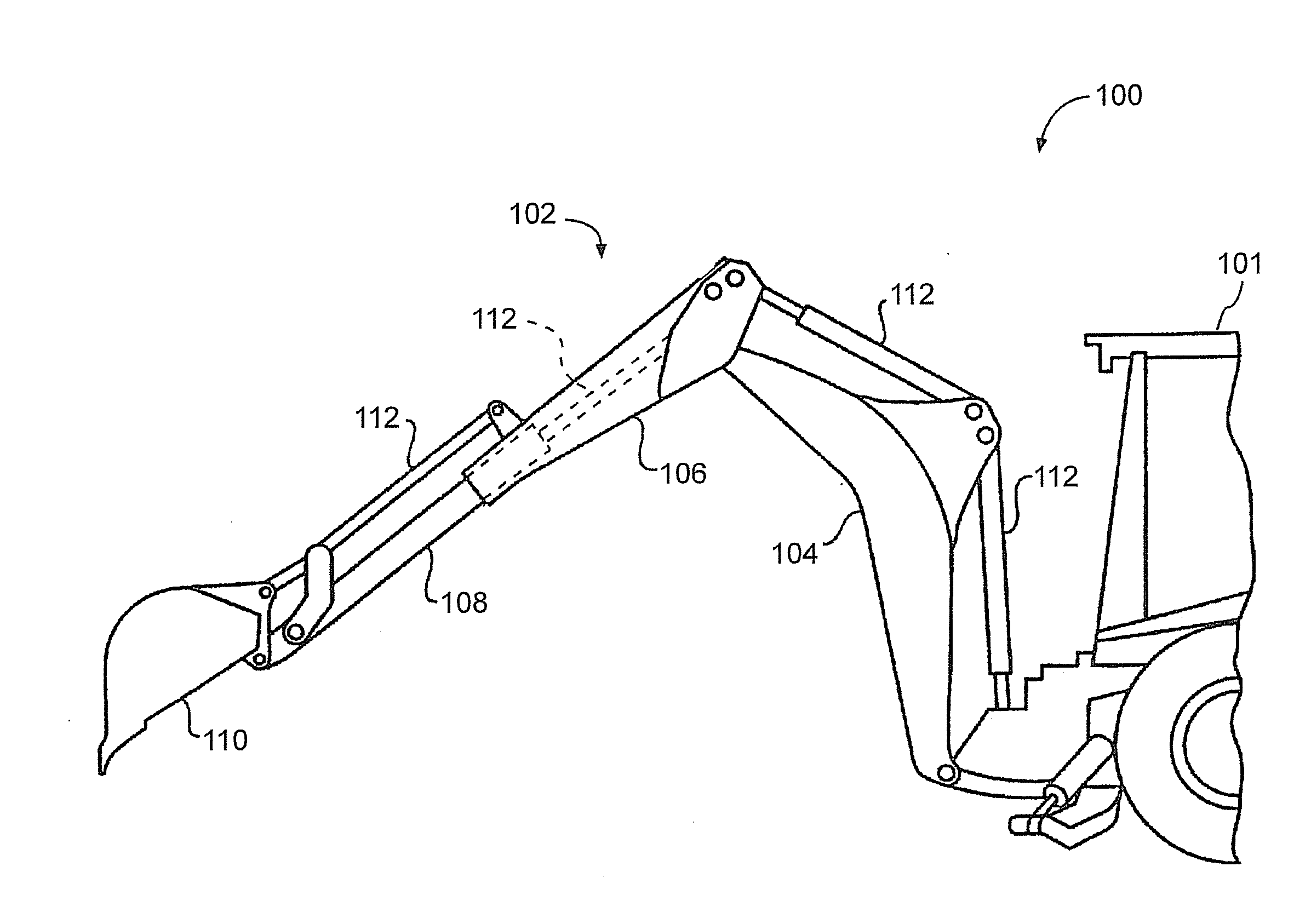
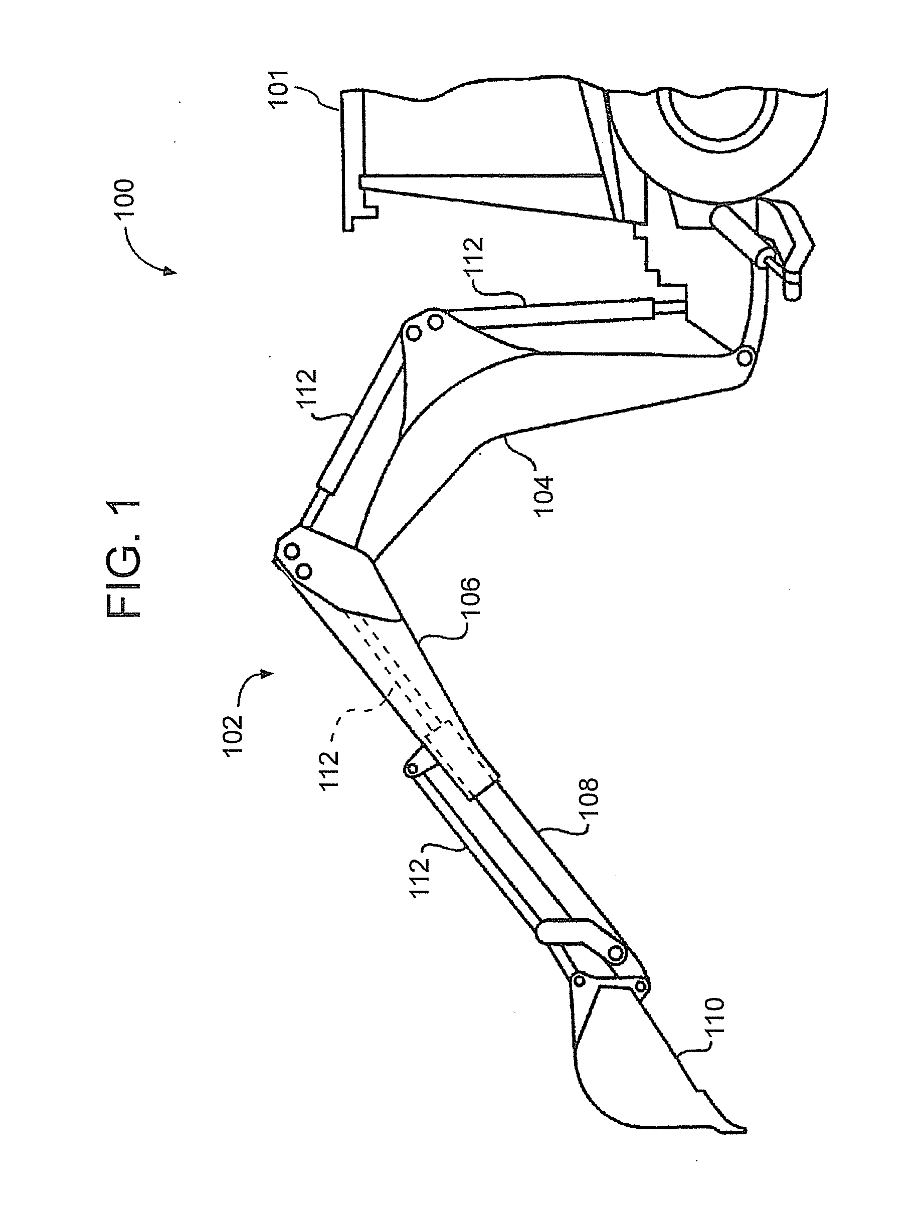
[0016]Referring now to the drawings, FIG. 1 illustrates an exemplary embodiment of a relevant portion of a work machine 100. The work machine 100 may be used for a wide variety of earth-working and construction applications. Although the work machine 100 is shown as a backhoe loader, it is noted that other types of work machines 100, e.g., excavators, front shovels, material handlers, and the like, may be us...
PUM
 Abstract
Description
Claims
Application Information