
Optical topographic imaging

a topographic image and optical technology, applied in the field of optical imaging, to achieve the effect of reducing artifacts and changing the contrast of topographic images

Active Publication Date: 2012-10-11
HID GLOBAL CORP
View PDF14 Cites 10 Cited by
  • Summary
  • Abstract
  • Description
  • Claims
  • Application Information

AI Technical Summary

Benefits of technology

[0011]The topography of the surface of the object may be defined by a topographic image, to which a transformation may be applied for certain effects. For example, the transformation may change a contrast of the topographic image, may reduce artifacts due to specular light within the topographic image, or may binarize the topographic image. These transformations may, moreover, also be determined with a machine-learning process.

Problems solved by technology

Alternatively, if skin of the proper index of refraction is in optical contact with the platen, the TIR at this location is frustrated, allowing light to traverse the platen-skin interface.

Method used


Image

  • Optical topographic imaging
  • Optical topographic imaging
  • Optical topographic imaging

Examples


Embodiment Construction

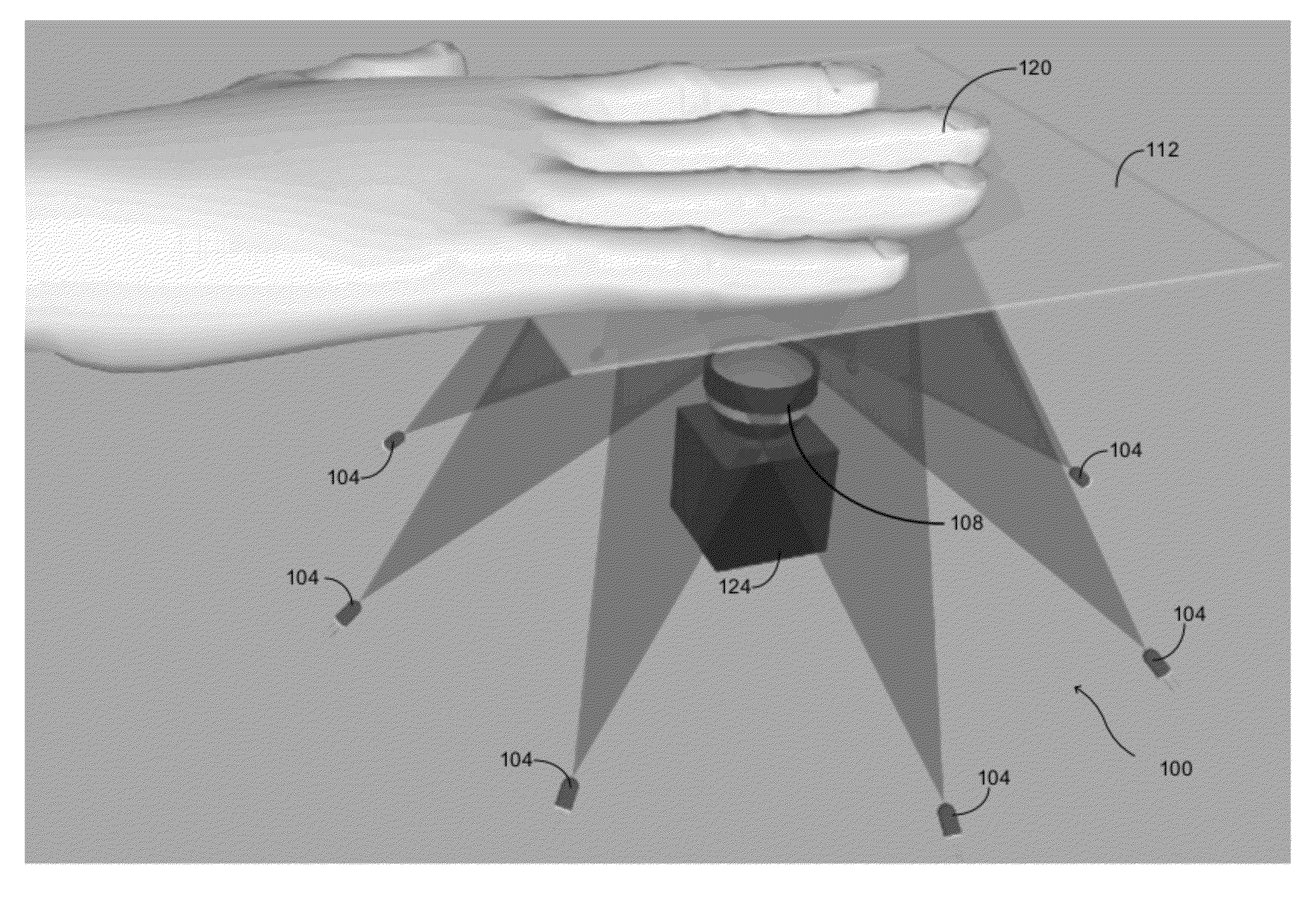
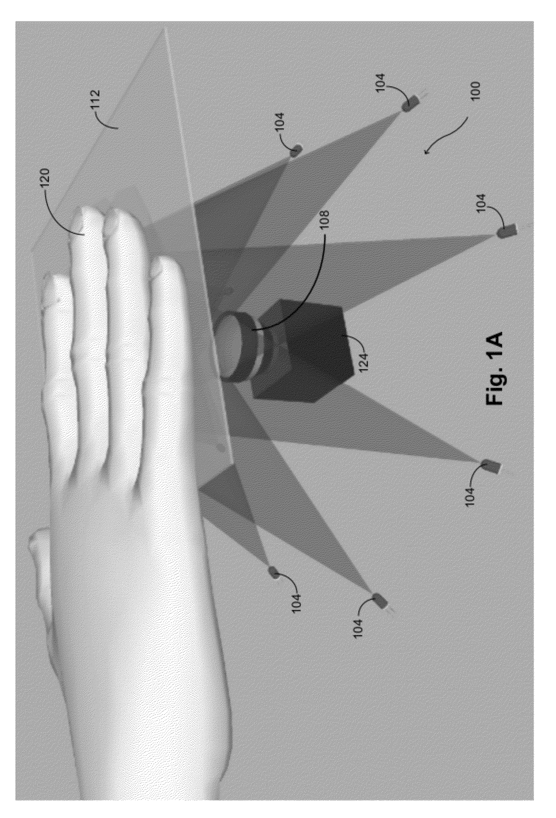
[0024]Embodiments of the invention are directed generally to methods and devices that use optical topographic imaging for imaging an object. These methods and devices find a variety of applications that include fingerprint and machined-barcode imaging among others. While the description that follows sometimes makes specific reference to fingerprint and / or machined-barcode imaging for purposes of illustration, this is not intended to be limiting. More generally, the methods and devices of the invention may be used with any object that has topographical features that are of interest. For example, other parts of the hand (such as the palm) or other body parts may be imaged by the methods and devices described herein. Measurements of a variety of manufactured goods, such as surface finishes of cast or machined parts may be performed. Scratches and other forensic details from bullets and other such objects may also be gathered using the methods and devices described herein.

[0025]It is sp...


PUM


Abstract

Methods and devices of studying a predefined portion of an object having a feature of interest are disclosed. The feature of interest defines a class of objects that includes the object. Light sources directly illuminate the object from different illumination directions. The light sources are maintained in a stable configuration relative to the object. For each illumination direction, an image is generated from light scattered from the object with a camera maintained in a stable configuration relative to the light sources. A methodology derived from machine learning for the class of objects is applied to filter the generated images are filtered for a characteristic consistent with the fetaure of interest. Surface gradients are determined from the filtered images and integrated to generate a topography of a surface of the object.

Description

CROSS-REFERENCE TO RELATED APPLICATION[0001]This application is a nonprovisional of, and claims the benefit of the filing date of, U.S. Prov. Pat. Appl. No. 61 / 473,860, entitled “OPTICAL TOPOGRAPHIC IMAGING,” filed Apr. 11, 2011, the entire disclosure of which is incorporated herein by reference in its entirety.BACKGROUND OF THE INVENTION[0002]This application relates generally to optical imaging. More specifically, this application relates to optical topographic imaging.[0003]There are a variety of applications in which it is desirable to study an object in order to analyze its topographical features. One particular example is fingerprint imaging, in which the topographical pattern of ridges is commonly used in identification applications, either to provide a mechanism for identifying a person from fingerprints or to verify a purported identity of a person based on that person's fingerprints.[0004]Most fingerprint-collection methods that are currently used rely on measuring charact...

Claims


Application Information

Patent Timeline
Patent Type & Authority Applications(United States)
IPC IPC(8): G06K9/62H04N7/18G06V10/145G06V10/60
CPCG06T7/0073G06K9/00033G06K9/00013G06T2207/10152G06T7/586G06V40/1312G06V40/1394G06V40/40G06V10/145G06V10/60
Inventor MUELLER, HORST ARNOLDMARTIN, RYAN ERICROWE
Owner HID GLOBAL CORP
Learn More