
Migler's windmill as a lamppost-windmill, and with sails mounted on a common mast, and with horizontally yoked sails, and as a river-turbine, and as a windmill-sailboat

a technology of windmills and lamps, which is applied in the direction of windmills or wind turbines, electric generator control, renewable energy generation, etc., can solve problems such as machine destruction

Inactive Publication Date: 2009-06-25
MIGLER BERNARD
View PDF22 Cites 13 Cited by
  • Summary
  • Abstract
  • Description
  • Claims
  • Application Information

AI Technical Summary

Benefits of technology

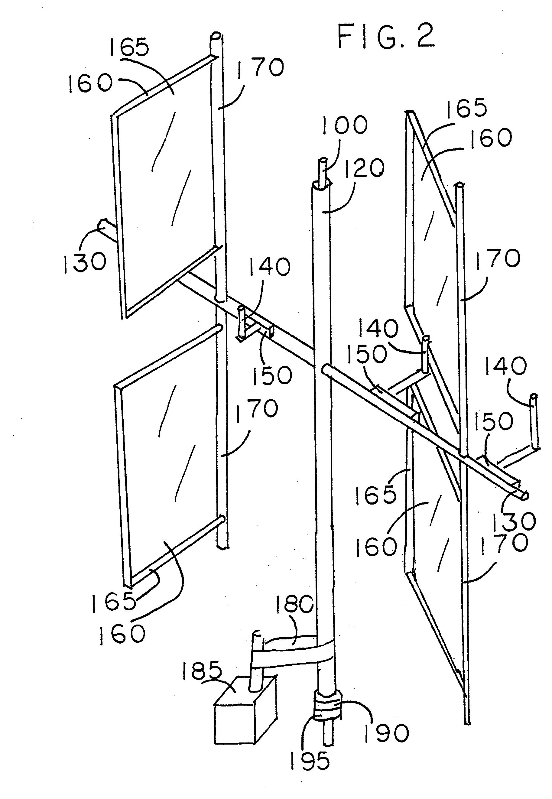
[0007]In Migler's vertical axis wind turbine, sails may be mounted both above and below a horizontal arm, with sail restraints for every sail. In one of the inventions described here, the sail restraints for the lower (or upper) sail are eliminated by yoking the upper and lower sails to a common mast. The result is a reduction in cost and complexity.
[0008]In Migler's vertical axis wind turbine two or more sails can be mounted horizontally along a horizontal arm, with each sail having its own sail restraints. The sails must be kept a sufficient distance apart so as not to collide with each other. For example if the width of each sail is 10 feet, then the masts for the sails must be mounted at least 20 feet apart. If the masts could be mounted say 12 feet apart, then more sails could be mounted along a horizontal arm. In one of the inventions described here the masts are mounted closer together by means of a yoke between the masts. The yoke prevents collisions between the sails.
[0009]A recent attempt to install a horizontal axis (wind) turbine in the East River of NYC failed, with the destruction of the machine for unknown reasons. Since the East River is actually a tidal estuary, that is, the flow of water changes direction with the tide. This change creates a problem for a horizontal axis machine since the machine has to reverse the direction it is facing with each change in the direction of flow of the water. Migler's vertical axis wind turbine solves this problem. When it is submerged and adapted as a river-windmill, it does not need to be reversed with each change in direction of flow of the water. This is due to the fact that Migler's horizontal axis machine rotates in a constant direction, regardless of the direction of the wind, or in this case, the direction of flow of the water.
[0011]Sailboats can sail in any direction except directly into the wind, and cannot sail when there is no wind. In the embodiment of Migler's vertical axis windmill described here the windmill is mounted on a boat. The energy of the wind is used to drive a generator which provides electrical energy for an electric motor which rotates a drive shaft that turns a propeller in the water A conventional rudder controls the direction of movement of the sailboat. Pontoons provide stability during crosswinds. Since the windmill rotates in a constant direction regardless of the direction of the wind the sailboat can sail in any direction. In addition, excess electrical energy is stored as electrical energy in a battery on the boat. The energy stored in the battery is then used to drive the electric motor when there is no wind. In another embodiment the rotary motion of the tower collar is translated directly into rotary motion of a horizontal shaft to which the propeller is secured.

Problems solved by technology

A recent attempt to install a horizontal axis (wind) turbine in the East River of NYC failed, with the destruction of the machine for unknown reasons.
This change creates a problem for a horizontal axis machine since the machine has to reverse the direction it is facing with each change in the direction of flow of the water.

Method used


Image

  • Migler's windmill as a lamppost-windmill, and with sails mounted on a common mast, and with horizontally yoked sails, and as a river-turbine, and as a windmill-sailboat
  • Migler's windmill as a lamppost-windmill, and with sails mounted on a common mast, and with horizontally yoked sails, and as a river-turbine, and as a windmill-sailboat
  • Migler's windmill as a lamppost-windmill, and with sails mounted on a common mast, and with horizontally yoked sails, and as a river-turbine, and as a windmill-sailboat

Examples


Embodiment Construction

1) Lamppost-Windmill

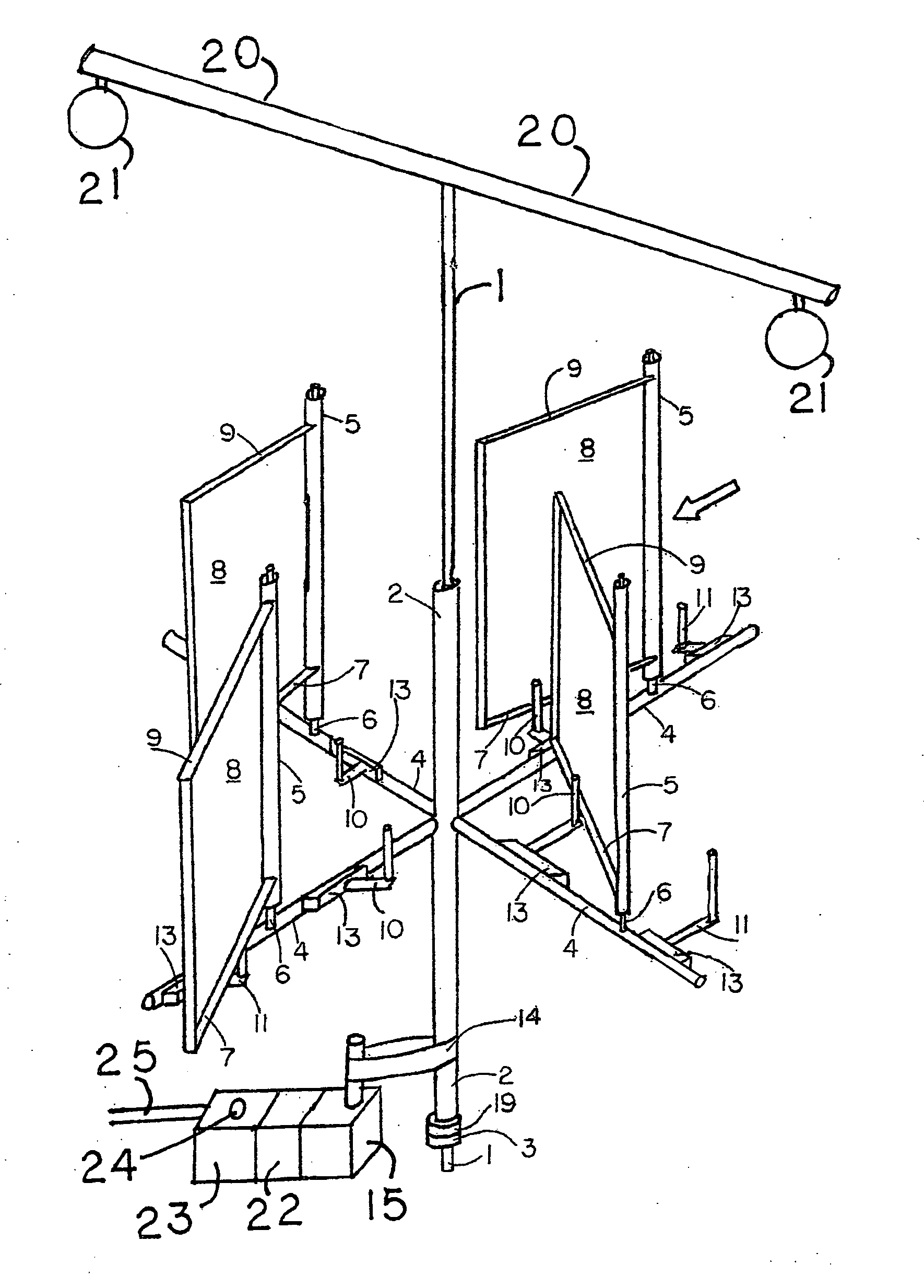
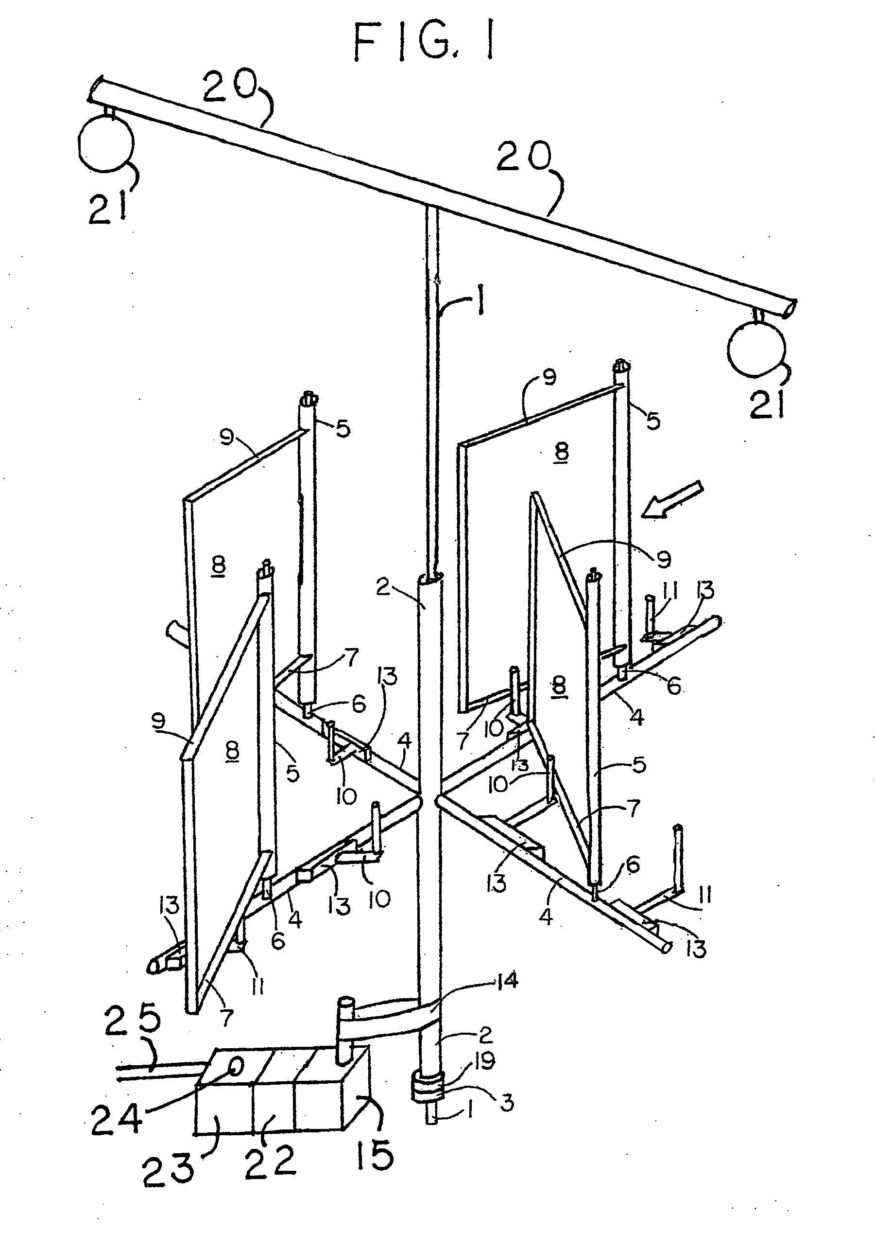
[0022]Referring now to the drawing in FIG. 1 there is shown a three dimensional drawing of Migler's vertical axis windmill adapted as a lamppost-windmill. The reader is referred to that patent for a detailed description of each part of the windmill and the operation of its adjustable sail restraints and motorized sail restraint controllers.

[0023]The arrow in FIG. 1 indicates the direction of the wind. The lamppost-tower 1 has support arms 20 that are secured to the tower 1. Lamps 21 that can illuminate a roadway are connected to the support arms 20. The tower 1 has a rotatable tower collar 2. Horizontal arms 4 are secured to the rotatable tower collar 2. Sail restraints 10 and 11 and motorized sail restraint controllers 13 are secured to each horizontal arm 4. Masts 6 are secured to the horizontal arms 4 between sails restraints 10 and 11. Each mast 6 has a rotatable mast collar 5. Booms 7, sail frames 5 and sails 8 are secured to each mast collar 5. The tower co...


PUM


Abstract

The disclosure presents several embodiments of Migler's vertical axis windmill. In the first, the windmill is adapted as a windmill-lamppost which stores electrical energy during daylight and operates the lamps at night. In the second, some sail restraints are eliminated by mounting sails on a common mast. In the third, a yoke allows sails to be mounted close together on a horizontal arm and also eliminates some sail restraints. In the fourth, Migler's vertical axis windmill is submerged in a river, with additional generators used to harness the slow movement of the water. In the fifth, a boat is powered by Migler's vertical axis windmill using direct drive of the propeller. In the sixth, a boat is powered by Migler's vertical axis windmill using a transmission to enhance propeller speed. In the seventh a boat is powered by Migler's vertical axis windmill using electrical energy to operate an electric motor. In the eighth, a boat is powered by Migler's vertical axis windmill using a storage battery to operate an electric motor when there is no wind. In the ninth a boat is powered by Migler's vertical axis windmill, having pontoons to provide stability during strong crosswinds.

Description

FIELD OF THE INVENTION[0001]The device relates generally to the field of windmills or wind turbines for the production of electricity. More specifically it relates to the field of vertical axis wind turbines.BACKGROUND OF THE INVENTION1) Lampost-Windmill[0002]Interstate highway lampposts expend considerable energy in lighting their bulbs at night. Means to reduce the cost of operating these lampposts would be useful. In an embodiment of Migler's vertical axis windmill (U.S. Pat. No. 6,926,491 B2 and USPTO publication number US-2007-0248450-A1; patent allowed but not yet issued) hereby incorporated by reference) as a lamppost-windmill, the tower of the lamppost becomes the tower of the windmill. The invention reduces the cost of operating these lampposts by harnessing and storing the energy of the wind during daylight and using that stored energy to light the bulbs at night.2 and 3) Common Mast and Yoked Pairs of Sails[0003]In Migler's vertical axis wind turbine, each sail requires t...

Claims


Application Information

Patent Timeline
Patent Type & Authority Applications(United States)
IPC IPC(8): F03D9/00
CPCF03B17/065F03D3/067F03D9/021F05B2240/911Y02E10/74F05B2240/932Y02E10/28Y02E10/728F05B2240/931F03D9/11Y02T70/5236Y02E10/30Y02E70/30F03D9/25F03D9/32F03D15/10F03D9/007Y02E10/20
Inventor MIGLER, BERNARD
Owner MIGLER BERNARD
Learn More