Spoke wheel

a technology of compression spokes and spokes, which is applied in the direction of spoked wheels, mechanical equipment, transportation and packaging, etc., can solve the problems of reducing the perimeter of the rim by up to 2 inches, allowing the use of a greater number of compression spokes, and reducing the lateral rigidity of almost constant, so as to increase the (buckling) strength, the lateral rigidity is almost constant, and the outer diameter is greater

Inactive Publication Date: 2009-06-25
MAVIC SA
View PDF27 Cites 15 Cited by
  • Summary
  • Abstract
  • Description
  • Claims
  • Application Information

AI Technical Summary

Benefits of technology

[0020]In particular, the spoked wheel according to the invention, which is a spoke wheel including a peripheral rim, a central hub, and individual connecting spokes between the rim and the hub, the spokes, in the free state, being assembled without tension or compression between the rim and the hub, and with each spoke being able withstand a compression load of at least 60 decaNewtons (daN) without buckling. In addition, the wheel has a greater number of spokes than compression spoke wheels and comprises, for example, more than ten spokes. Such a construction has the advantage of reducing all of the stresses within the spokes of the rim to zero, in the free state. Consequently, the spokes are provided to be capable of withstanding a substantial compressive force, without buckling, in order to be able to withstand the forces being exerted in the wheel during use.
[0031]Spokes according to the invention can have a non-constant cross section in the longitudinal direction, and the spoke can have a cross section having a variable shape along the longitudinal direction, such as, for example, a larger cross section in the median zone in order to withstand buckling more efficiently.

Problems solved by technology

Indeed, these spokes, which must withstand compressive forces, have a much larger cross section than the usual common spokes to avoid buckling, and their dimensions themselves do not allow a greater number of compression spokes to be used.
First, the spoke tension produces compressive stresses in the rim body. It is estimated that for a road bike wheel having 36 spokes, with each spoke being tensioned to 1000 Newtons, the compressive force resulting in the area of the rim body is 5730 Newtons, which produces a compressive stress of 88 MegaPascals (MPa), which, for a material commonly used for a rim (aluminum 6106, for example), already represents 40% of the material inherent strength potential (220 MPa). In other words, this resultant compression already weakens the rim considerably.
In addition, for a rim 622 millimeters (mm) in diameter, this compressive force leads to a reduction in the rim perimeter of up to 2.5 mm, which, naturally, can have an impact on the connection between the rim and the tire, and can lead to ill-timed tire roll offs and accidents.
Second, the spoke tension is exerted on the rim locally.
These repeated cycles result in damage to the spoke, the hub, or the rim, and this all the more quickly as the tension in the spoke is high.
Consequently, the currently available tension spoke wheels do not have an optimal service life.

Method used


Image

  • Spoke wheel
  • Spoke wheel
  • Spoke wheel

Examples


Embodiment Construction

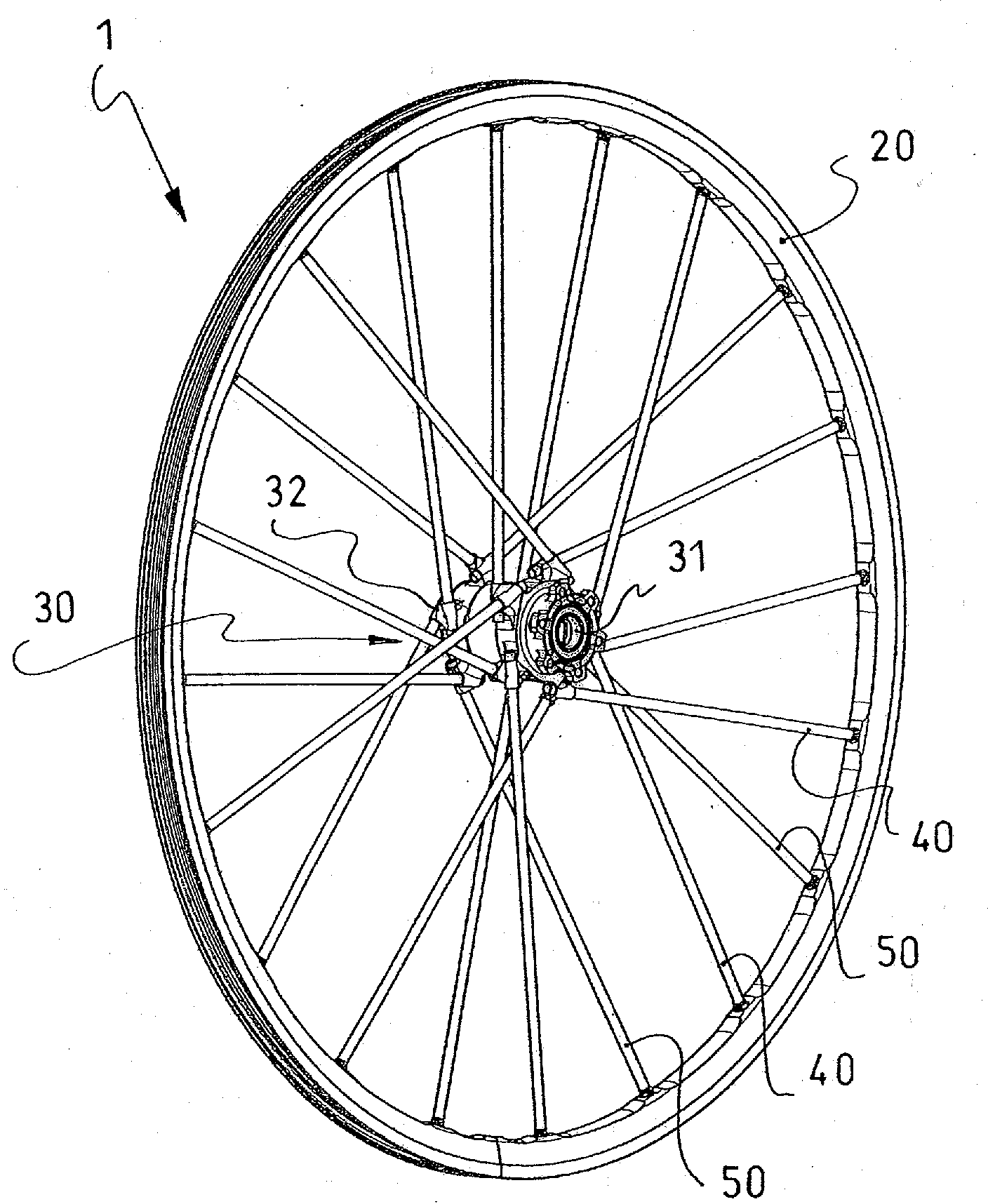
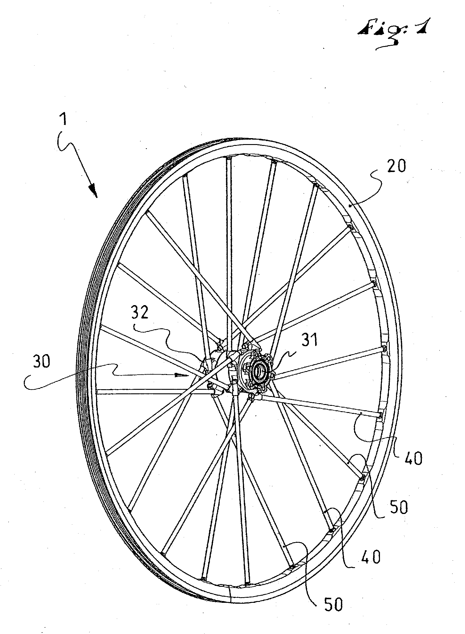
[0045]The wheel 1 according to the invention, shown in FIG. 1, conventionally includes a peripheral rim 20, a central hub 30, and connecting spokes 40, 50 extending between the rim 20 and the hub 30. The spokes 40, 50 are distributed in two sets, each set of spokes 40, 50 being attached to one end 31, 32, respectively, of the hub 30, and extending from the end 31, 32, respectively, from the hub towards the rim 20. The spokes 40, 50, respectively, are attached alternatively to the rim and are distributed evenly along the periphery thereof. They can also be distributed, as known, on the various sets in predetermined groups on the tension spoke wheels, as described, for example, in U.S. Pat. No. 6,145,938.

[0046]Each set of spokes 40, 50 comprises ten in number, or a total of twenty, which is a much greater number than the number of compression spokes in a so-called compression spoke wheel, having a maximum of six compression spokes, and a smaller number than the usual number of spokes ...


PUM

PropertyMeasurementUnit
inner diameteraaaaaaaaaa
compressive forceaaaaaaaaaa

Abstract

The invention relates to a spoke wheel that includes a peripheral rim, a central hub, and individual connecting spokes between the rim and the hub. In their free state, the spokes of the wheel are mounted without tension or compression between the rim and the hub, and each spoke can bear a compression load of at least 60 daN without bowing. Furthermore, the wheel includes a play-free connection or bilateral connection device for connecting at least one end of each spoke to the rim or the hub.

Description

BACKGROUND OF THE INVENTION[0001]1. Field of the Invention[0002]The invention relates to a new design of a compression spoke wheel, in particular a cycle wheel. The invention also relates to a compression spoke wheel having at least one such compression spoke, as well as a rolling apparatus, in particular a cycle, equipped with at least one such wheel.[0003]2. Description of Background and Other Information[0004]The wheel has existed since the mists of time. The first wheels were solid wheels. A first improvement consisted in building compression spoke wheels, which were lighter. The spokes of such wheels were biased in compression and in flexion by a rim. Then, the wheel was ringed by a metal hoop and the compression spokes were pre-stressed in compression. The patent document CH 91759 describes such a mode of construction.[0005]The invention of the tension wire spoke wheel goes back to around 1866, and is credited to Eugène Meyer. This invention made it possible to build wheels wi...

Claims


Application Information

Patent Timeline
Patent Type & Authority Applications(United States)
IPC IPC(8): B60B1/04
CPCB60B1/003B60B1/0253B60B1/0284B60B1/041B60B1/042B60B1/045Y10T29/49515B60B1/14B60B21/025B60B21/062B60B21/064B60B27/0005B60B27/023B60B1/048
Inventor MERCAT, JEAN-PIERREMOUZIN, OLIVIER
Owner MAVIC SA
Why Eureka
Try Eureka