Image forming apparatus, image forming method, and computer-readable storage medium

Active Publication Date: 2009-06-25
CANON KK
View PDF13 Cites 8 Cited by
  • Summary
  • Abstract
  • Description
  • Claims
  • Application Information

AI Technical Summary

Benefits of technology

[0029]Provided are an image forming apparatus and method thereof, directed to improving both productivity and output image quality when performing printing of a large number of copies.

Problems solved by technology

Stopping a job during printing executing directly relates to decreased productivity of the printing apparatus.
However, the output image quality immediately following calibration and the output image quality immediately preceding the next calibration has a large image quality difference (density difference).
However, while executing calibration processing, the job during printing output executing must be stopped, whereby the function of a POD high-speed device is not satisfied.
That is to say, none of the current technologies described above offer solutions to the problem needed particularly for a POD high-speed device to achieve both high productivity and improved output image quality.

Method used


Image

  • Image forming apparatus, image forming method, and computer-readable storage medium
  • Image forming apparatus, image forming method, and computer-readable storage medium
  • Image forming apparatus, image forming method, and computer-readable storage medium

Examples


first embodiment

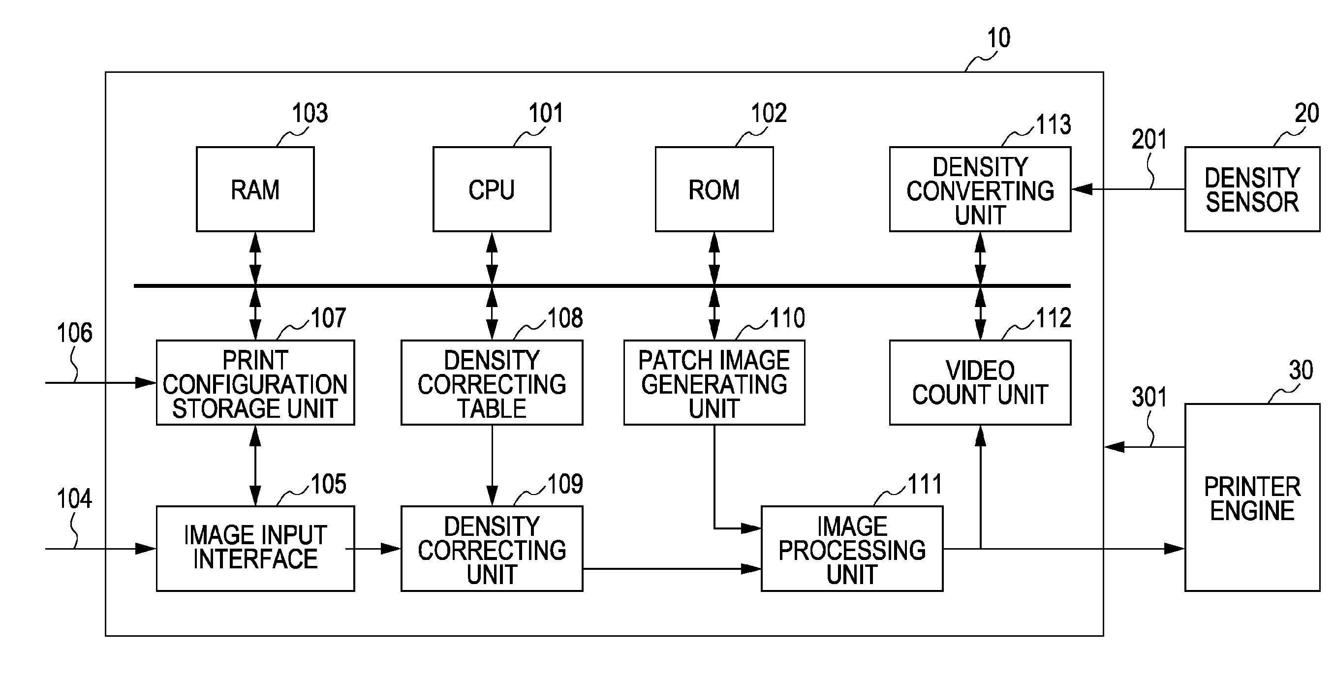
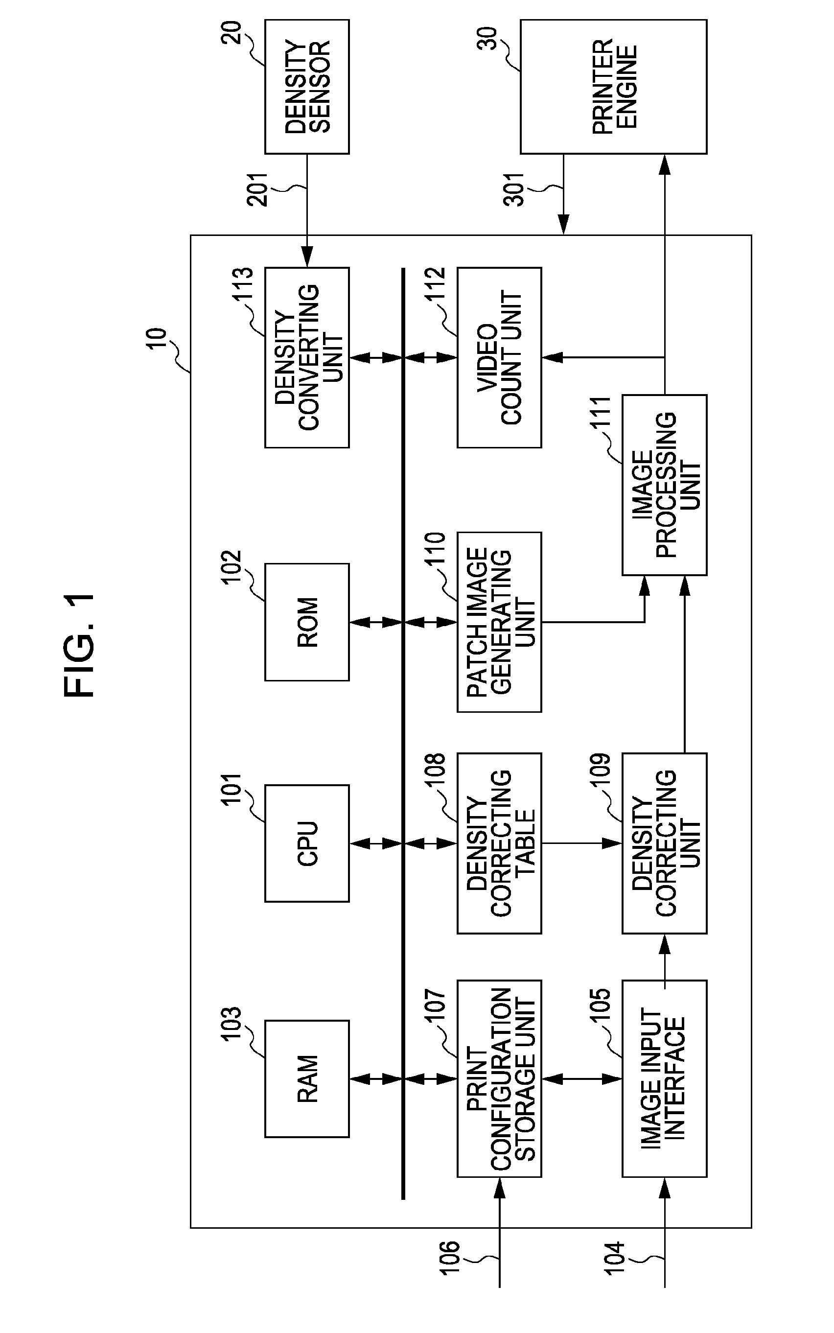
[0053]FIG. 1 is a block diagram illustrating an image forming apparatus according to a first embodiment. The image forming apparatus according to the present embodiment is made up of an image forming unit 10 to perform taking in of image data and forming an image, a density sensor 20 to measure a density value of a patch image data at the time of calibration operation, and a printer engine 30 to print image data output by the image forming unit 10. The image forming apparatus according to the present embodiment is, for example, a printing apparatus, photocopier, or MFP (Multi Function Printer) having the combined functions of a facsimile / copier / printer, and so forth.

[0054]Also, the image forming unit 10 is made up of a processing block as described below. 101 denotes a central processing unit (hereafter, CPU) to configure the entire image device, 102 denotes a read-only memory (hereafter, ROM) that stores the control program of the CPU 101. 103 denotes a random-access memory (hereaf...

second embodiment

[0114]Next, a second embodiment will be described. With the first embodiment, in the case that the printing configuration is number-of-copies printing configuration, one copy of image data wherein image density is printed is defined as a unit. With the second embodiment, the case of changing the image density definition in the case of number-of-copies printing configuration will be described. Note that with the description of the second embodiment, in cases where the diagrams and reference numerals are the same as the description in the first embodiment, the same reference numerals will be used for description.

[0115]FIG. 7 shows an operation flow of the second embodiment. In the case that the input job is large number of copies printing, and the printing configuration is number-of-copies printing configuration, the CPU 101 performs confirmation of the number of pages to configure one copy (step S201). In the case that the number of pages making up one copy is less than predetermined...

third embodiment

[0147]Next, a third embodiment will be described. With the first embodiment and second embodiment, calibration operations are performed at predetermined timings within the limited number of copies according to the printing configuration, from the point-in-time that the job for printing execution is input. In other words, the density correcting table is set by measuring the density shift amount and holding the measured value for each case according to the image density defined with each printing configuration.

[0148]Conversely, with the third embodiment, a test print mode is provided, and within the mode operation thereof, the density shift amount is measured and held in the stage before printing a large amount of copies, according to the provided printing configuration.

[0149]Before printing a large number of copies, printing a test print is often performed rather than depending on a POD device. With the execution of the test printing, in the case that determination is made that there...


PUM


Abstract

A method that prints image data including multiple pages one copy at a time, and prints multiple copies, includes generating a patch image having multiple densities, forming the patch image on a photosensitive drum, and reading the density of the patch image, wherein generating the patch image, forming the patch image, and reading the density of the patch image are performed at a time of ending printing for certain copies.

Description

BACKGROUND OF THE INVENTION[0001]1. Field of the Invention[0002]The present invention relates to an image forming apparatus, image forming method, and a computer-readable storage medium in order to stabilize output features of an output apparatus.[0003]2. Description of the Related Art[0004]In recent years, print-on-demand (hereafter called POD) using a high-speed multi-function device has become common for printing work and copying work. POD efforts have advanced in general industries in order to self-manufacture meeting materials or proposals, and in design offices in order to perform prepress or printing of color comprehensive layout. Workflow of digital printing has permeated, with these industries centrally, and the usability and economy has becomes widely understood, and a market called “digital business printing” has been formed. Printing apparatuses applicable to this market not only outputs high quality printed material, but are printing apparatuses securing high production...

Claims


Application Information

Patent Timeline
IPC IPC(8): G06F15/00
CPCH04N1/32486H04N1/4078H04N1/40006
Inventor NAKAMURA, YASUYUKI
Owner CANON KK
Why Eureka
Try Eureka