[0008]An object of the present invention is to reduce the burden on the user when bringing up the camera head from the table side, in order to address the problems noted above.
[0012]arm shaft support module for giving shaft support such that the camera holding arm can rotate in relation to the table so that it is possible for the camera head to achieve an imaging stance for imaging the imaging-object from the table top side and a table side head stance close to the top surface of the table,
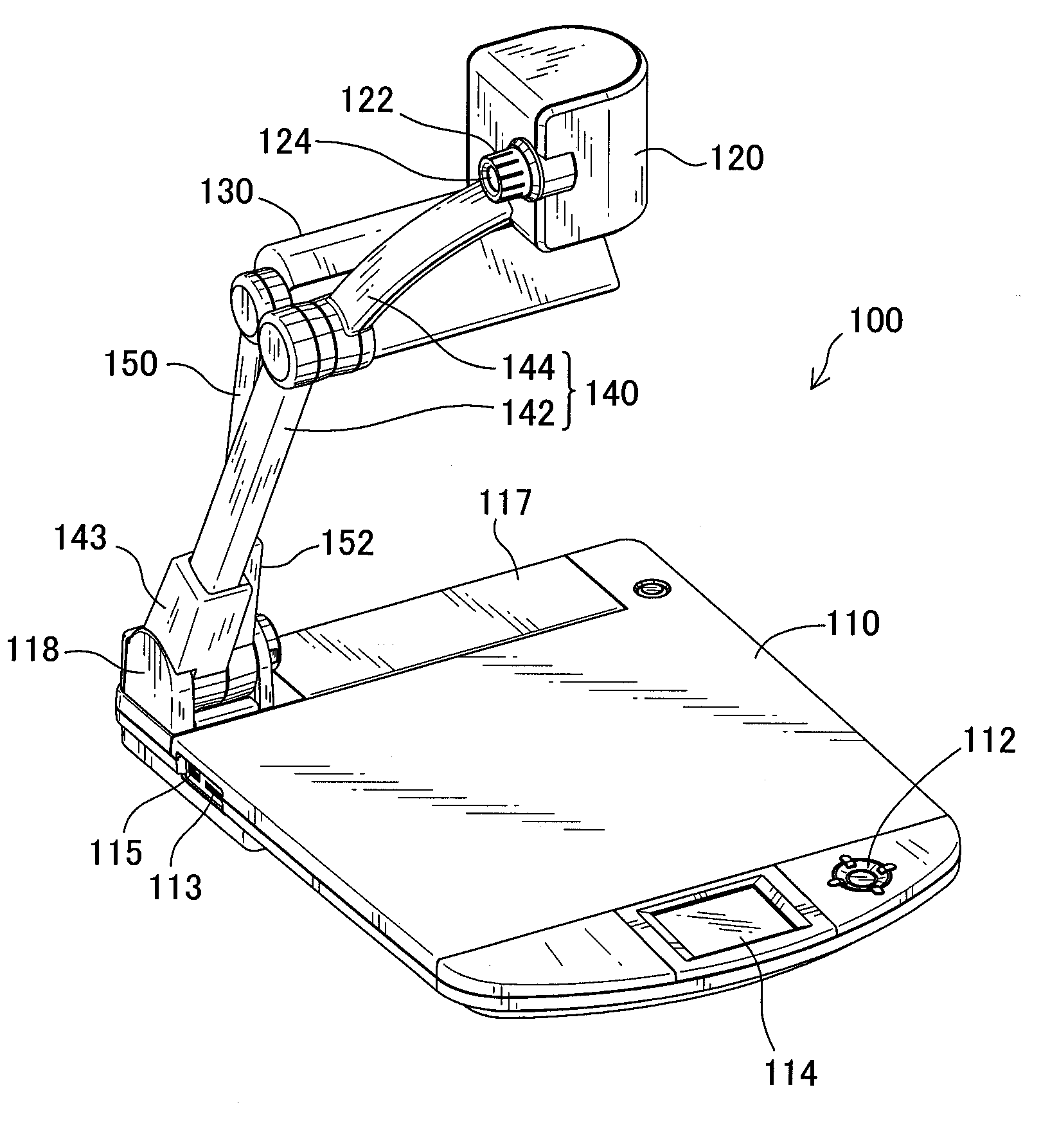
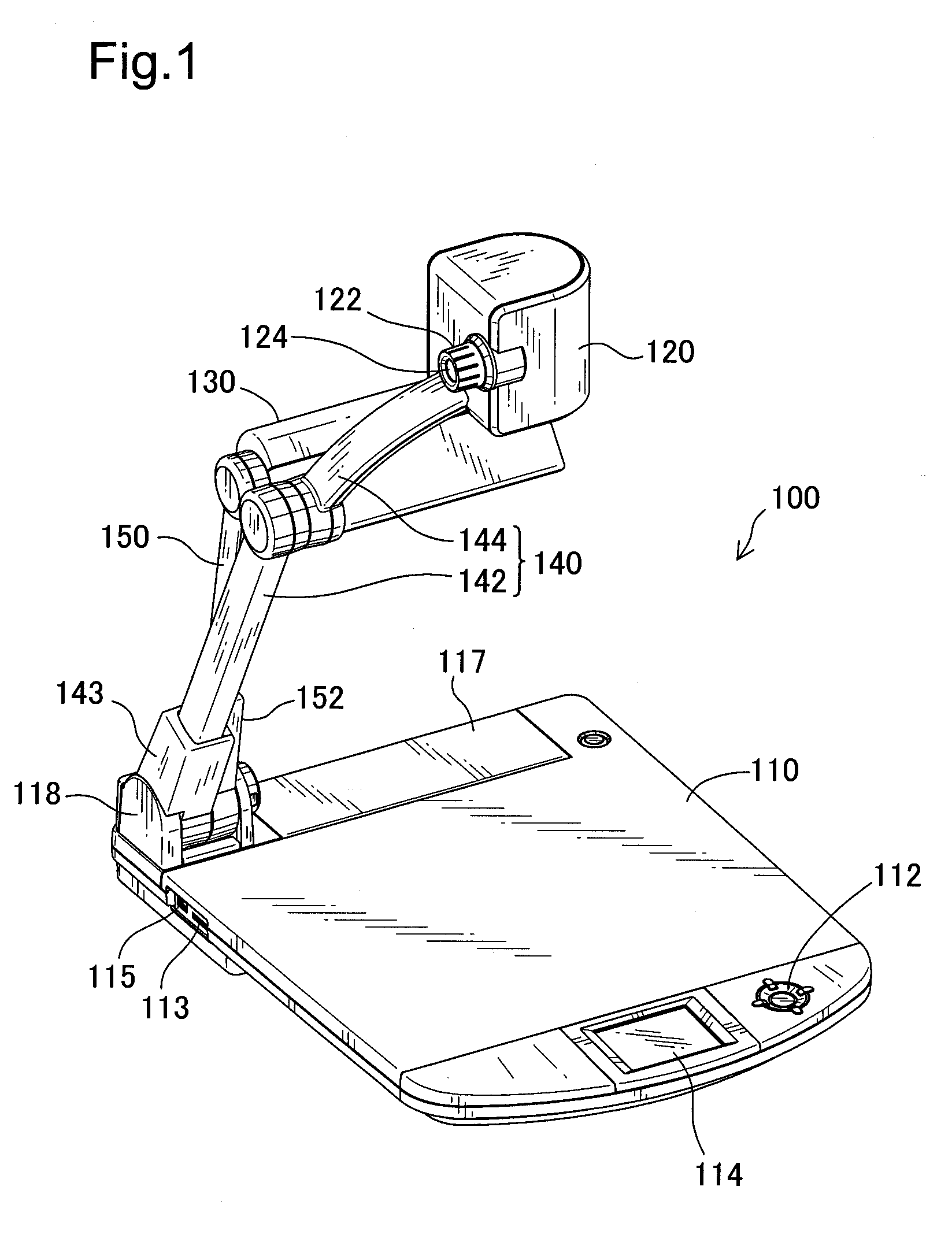
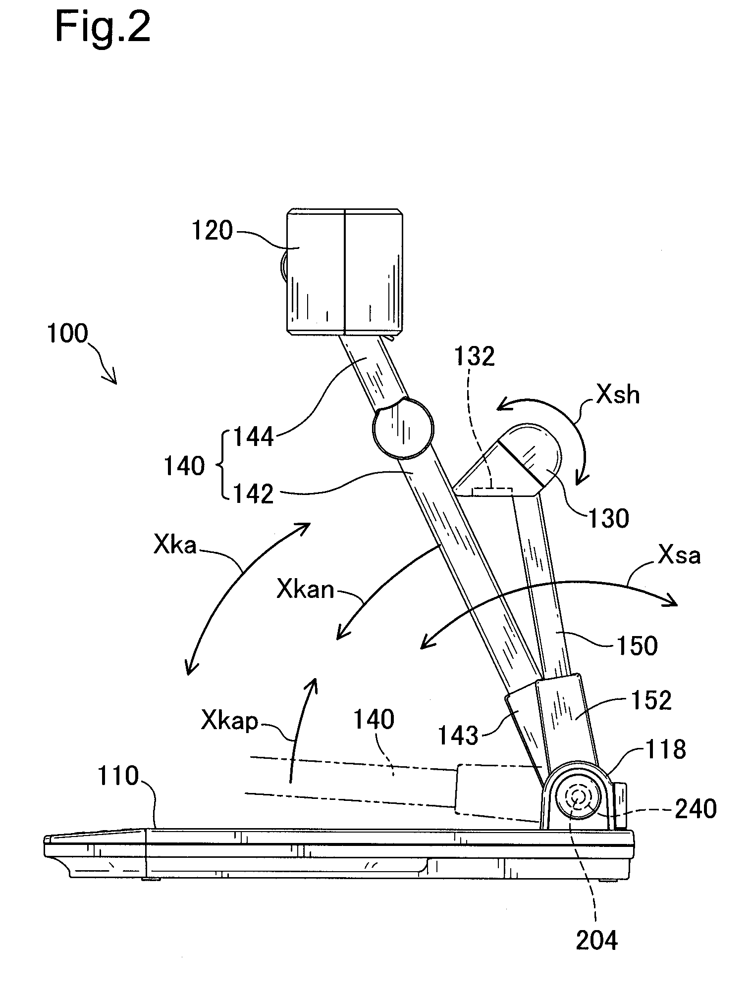
[0018]With the imaging device of the constitution noted above, the camera head with a camera built in is held by the camera holding arm, and this camera holding arm is rotatably supported so as to be able to turn freely in relation to the table by the arm shaft support shaft of the arm shaft support module. Thus, by rotating the camera holding arm, the camera head is able to achieve the imaging stance for imaging the imaging-object from the top side of the table and the table side head stance close to the top surface of the table.
[0020]When the camera head is in the table side head stance, the stance change resistance unit has resistance to the imaging side stance change of the camera holding arm, so the camera holding arm stops at this table side head stand position. When rotating the camera holding arm toward the imaging stance so as to overcome this resistance, the arm rotating operation for causing this stance change is an operation that rotates the camera holding arm by the imaging side stance change from the table side head stance toward the imaging stance, so the camera holding arm is released by the release unit from the frictional force exerted by the adjustment unit. Thus, when the user rotates the camera holding arm so as to cause this imaging side stance change, the user does not have to exert force on the camera holding arm for overcoming this frictional force, and the burden on the user is approximately only the weight of the camera head. Then, when the user puts his hand on the camera holding arm, and rotates it to bring it up to the imaging side stance of the camera head, or to any inclined position of the imaging side stance change process, for example, the inclined position for imaging the imaging-object from the side or a
diagonal direction, the rotating operation up to that position is done with a force corresponding to the weight of the camera head as described previously. Thus, it is possible to not place an excessive burden on the user. In fact, when the user removes his hand from the camera holding arm and stops the rotating operation of the imaging side stance change, at that point in time, the release by the release unit of the frictional force on the camera holding arm is cancelled, and the camera holding arm receives the frictional force adjusted by the adjustment unit and stops at the inclined position after rotating. Because of this, the camera head stops at the position above the imaging-object or at a position at the side or diagonal direction, so it is possible to do imaging of the imaging-object without interference.
[0022]It is possible to use various
modes for the imaging device described above. For example, it is possible to have the release unit interposed between the arm shaft support shaft and the camera holding arm and be mounted on the arm shaft support shaft, and to have it be a one way
clutch that allows only rotating of the camera holding arm with the imaging side stance change. By doing this, it is possible to lighten the operating burden of the user with a simple method of mounting a one way clutch.
[0023]It is also possible to have a stance change regulating unit be a mechanism that gives a sense of restraint that works together with a ball, a concave site in which the ball enters, and a spring that biases the ball toward the concave site. By doing this, in addition to the camera holding arm stopping at the table side head stance, when the user returns the camera holding arm to the table side head stance, it is possible to give the user a sense of restraint for the completion of the change to this stance, increasing convenience.

