
Automotive fuel tank fabrication apparatus

a technology for fabricating apparatus and fuel tanks, which is applied in the direction of domestic applications, other domestic articles, domestic articles, etc., can solve the problems of increasing the weight of molded fuel tanks, and achieves the effects of improving workability, reducing the weight of molded fuel tanks, and improving the impact resistan

Inactive Publication Date: 2009-06-25
FTS
View PDF5 Cites 28 Cited by
  • Summary
  • Abstract
  • Description
  • Claims
  • Application Information

AI Technical Summary

Benefits of technology

[0022]The built-in part holding unit includes the plurality of holding rods for holding the built-in part and the holding rods are made to hold the built-in part in the position where the built-in part confronts the cavities on the opening and closing sides of the blow mold when the blow mold is opened. Because of this, there is caused no situation in which the built-in part moves in a rotational direction relative to the holding rods, and the built-in part can be positioned in the rotational direction and a horizontal direction relative to the cavities in an ensured fashion, whereby the built-in part can be mounted in a predetermined position with respect to the rotational direction and the horizontal direction in the interior of the automotive fuel tank. Since the built-in part holding apparatus has the plurality of holding rods, a large built-in part can be mounted without any deformation of the built-in part.
[0034]Since the built-in part holding unit includes the plurality of holding rods for holding the built-in part, there is caused no such situation that the built-in part moves in the rotational direction relative to the holding rods, and the built-in part can be positioned in the rotational direction and the horizontal direction relative to the cavities in the ensured fashion. Since the built-in part holding apparatus has the plurality of holding rods, the large built-in part can be mounted without any deformation of the built-in part.

Problems solved by technology

In this case, however, since the built-in part 120 is set in the resin frame and is then secured to the inner circumferential surface of the outer wall of the fuel tank, labor hours have to be involved in cutting to remove the resin frame after the fuel tank has been molded, and with a small built-in part 120, a large resin frame has to be used, often resulting in a case where the weight of the molded fuel tank is increased.

Method used


Image

  • Automotive fuel tank fabrication apparatus
  • Automotive fuel tank fabrication apparatus
  • Automotive fuel tank fabrication apparatus

Examples


Embodiment Construction

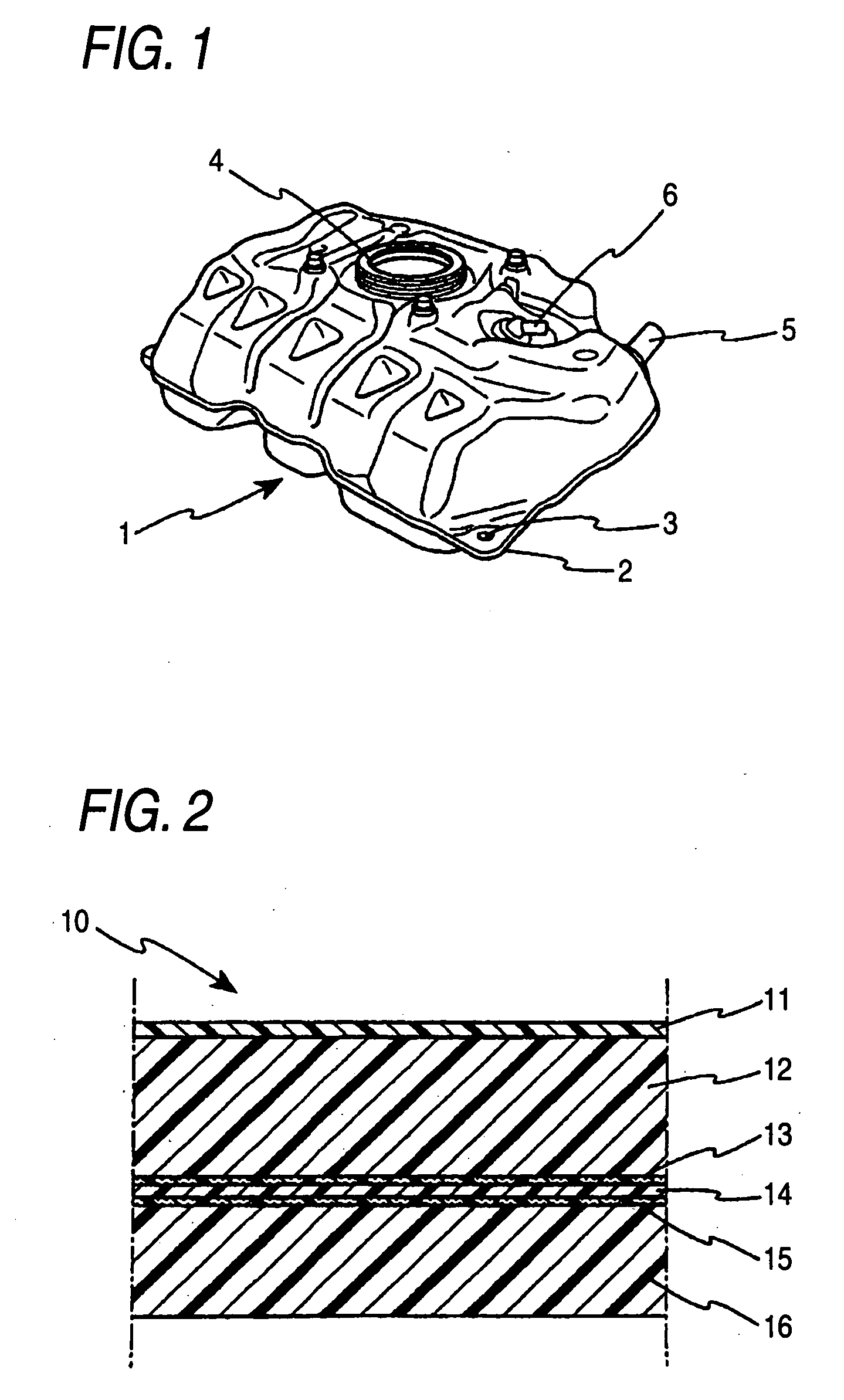
[0049]An automotive fuel tank 1 of an embodiment of the invention will be described based on FIGS. 1 to 10. FIG. 1 is a perspective view of a fuel tank 1 of an embodiment of the invention, and FIG. 2 is a partial sectional view of an outer wall 10 of the fuel tank 1 which is made from a thermoplastic synthetic resin.

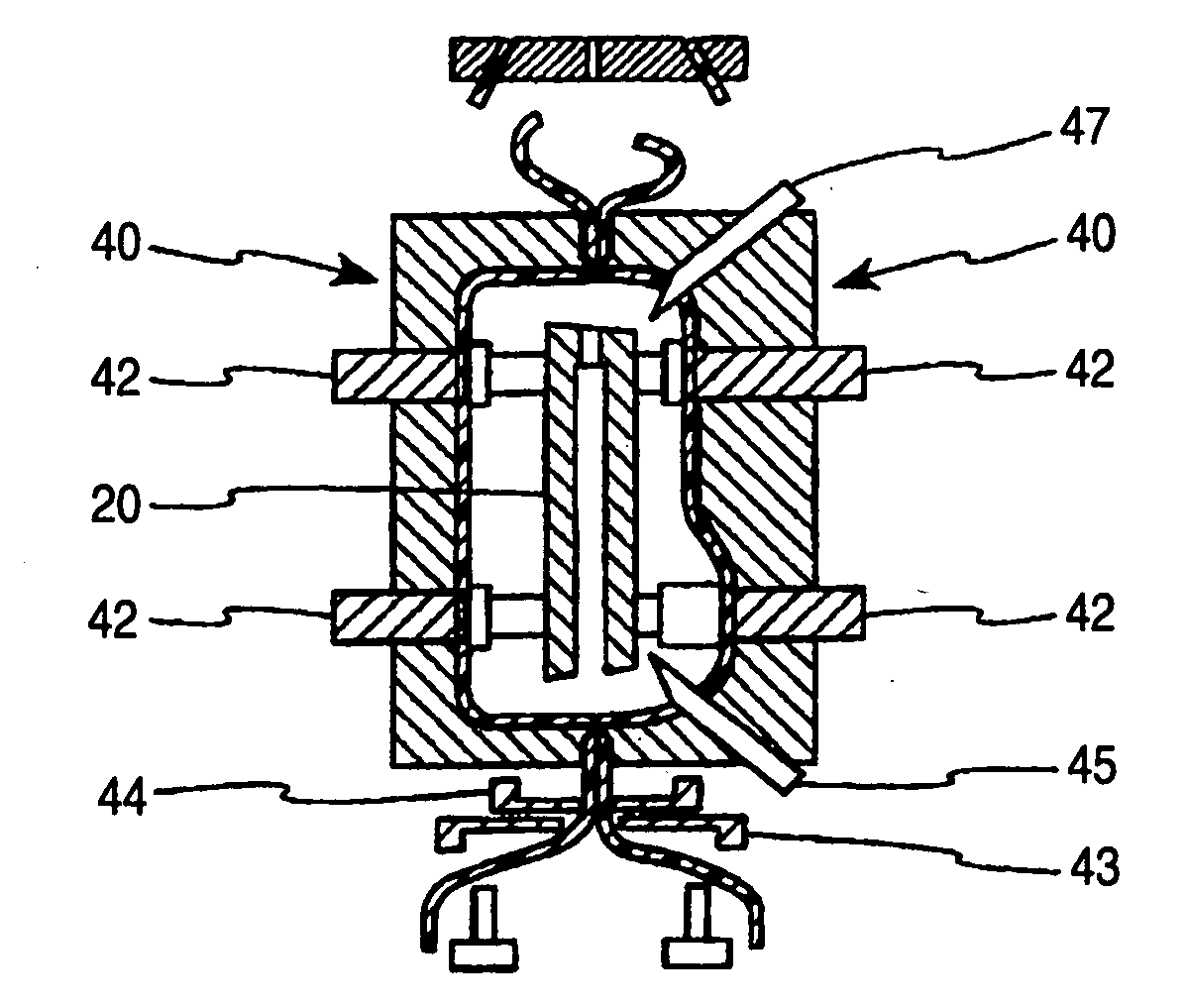
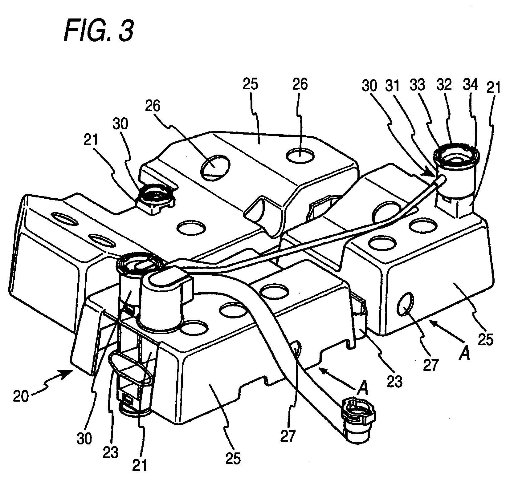
[0050]FIG. 3 is a perspective view showing a built-in part 20 which is mounted in an interior of the automotive fuel tank 1 which is used in the embodiment of the invention, and FIG. 4 is a perspective view of a fabrication apparatus of the automotive fuel tank 1 of the invention.

[0051]FIGS. 5 to 10 are drawings showing steps of blow molding the fuel tank 1.

[0052]As is show in FIG. 1, the fuel tank 1 which is fabricated in the embodiment of the invention has a pump unit mounting hole 4 formed in an upper surface of the tank for ingress and egress of a fuel pump (not shown) into and from the fuel tank 1. In addition, a fuel inlet hole 5 into which fuel is supplied from an...


PUM

PropertyMeasurementUnit
thicknessaaaaaaaaaa
thicknessaaaaaaaaaa
diametersaaaaaaaaaa

Abstract

An automotive fuel tank fabrication apparatus is provided. The automotive fuel tank has a blow mold and a built-in part holding unit. The built-in part holding unit includes a plurality of holding rods for holding a built-in part. The holding rods are made to freely advance and retreat in such a manner as to hold the built-in part in a position where the built-in part confronts cavities when the blow mold is opened and to retreat from the blow mold when the blow mold is closed with the built-in part left positioned in an interior of a parison. The holding rods are formed in such a manner that their diameters are reduced as they extend towards distal ends thereof and are inserted into insertion holes formed in the built-in part so as to hold the built-in part.

Description

BACKGROUND OF THE INVENTION[0001]1. Field of the Invention[0002]The present invention relates to a fabrication apparatus for an automotive fuel tank which is made from a thermoplastic synthetic resin and more particularly to a fabrication apparatus for an automotive fuel tank whose outer wall is formed from a thermoplastic synthetic resin through blow molding and which has a built-in part in an interior thereof[0003]2. Related Art[0004]Conventionally, metallic fuel tanks were used as fuel tanks for motor vehicles and the like. In recent years, however, fuel tanks made from thermoplastic synthetic resins have been in use due to thermoplastic resin materials being light in weight to satisfy increasing demands for vehicles which are light in weight, being free from rust, being easy to be molded into desired shapes.[0005]A blow molding approach has been used in many cases in fabricating automotive fuel tanks from thermoplastic resins because the blow molding approach facilitates the mol...

Claims


Application Information

Patent Timeline
Patent Type & Authority Applications(United States)
IPC IPC(8): B29C49/30
CPCB29C49/04B29C49/22B29C49/4242B29L2031/7172B29K2023/086B29K2067/00B29K2067/006B29K2023/065B29C49/42448B29C49/425
Inventor AOKI, TOMOHIDEYOSHIDA, YOSHINARI
Owner FTS
Learn More