

Outboard motor
a technology for outboard motors and motors, applied in the direction of auxillary lubrication, muscle operated starters, liquid cooling, etc., can solve the problems of excessive speed at the tip of the impeller blade, a plateau in the amount of fluid discharge, and a cavitation in the pump housing, so as to minimize the occurrence of cavitation, compact structure, and simple
- Summary
- Abstract
- Description
- Claims
- Application Information
AI Technical Summary
Benefits of technology
Problems solved by technology
Method used
Image

Examples
first preferred embodiment
[0035]A preferred embodiment of the present invention will hereinafter be described with reference to FIG. 1 through FIG. 6.
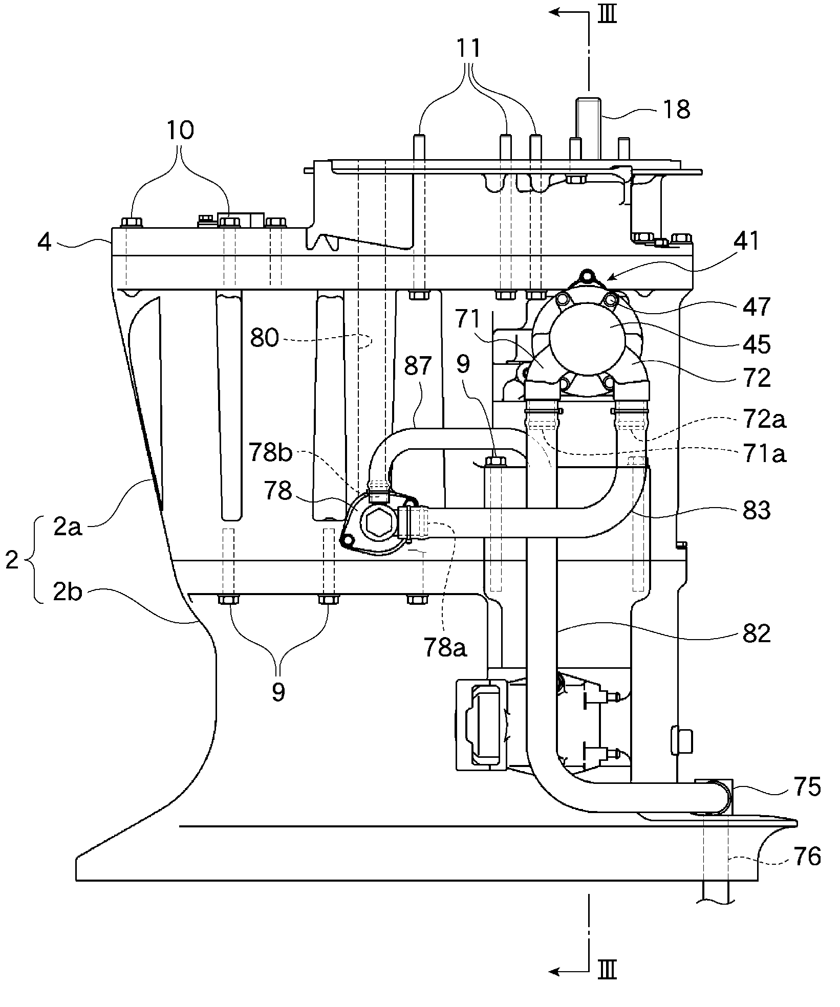
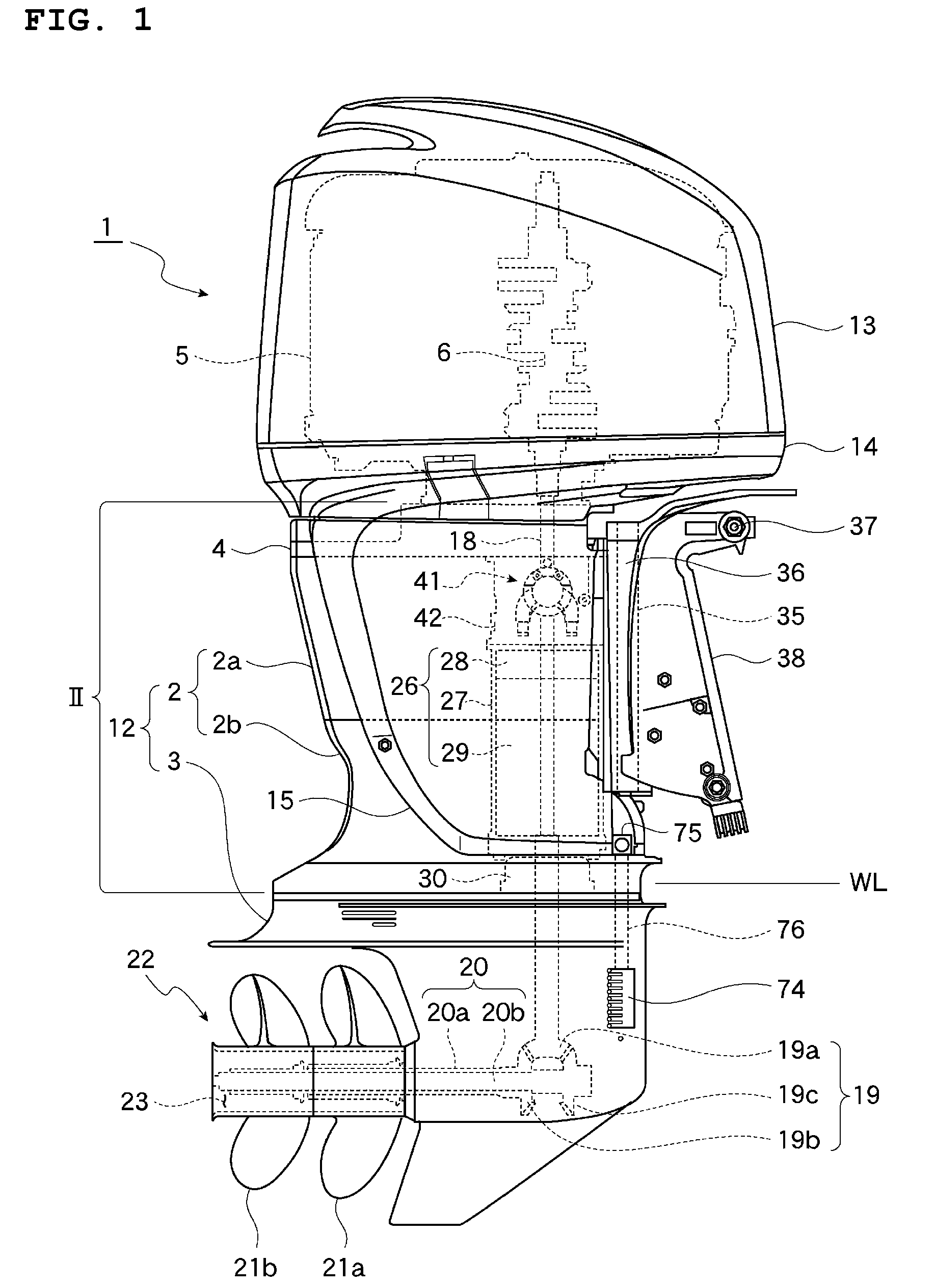
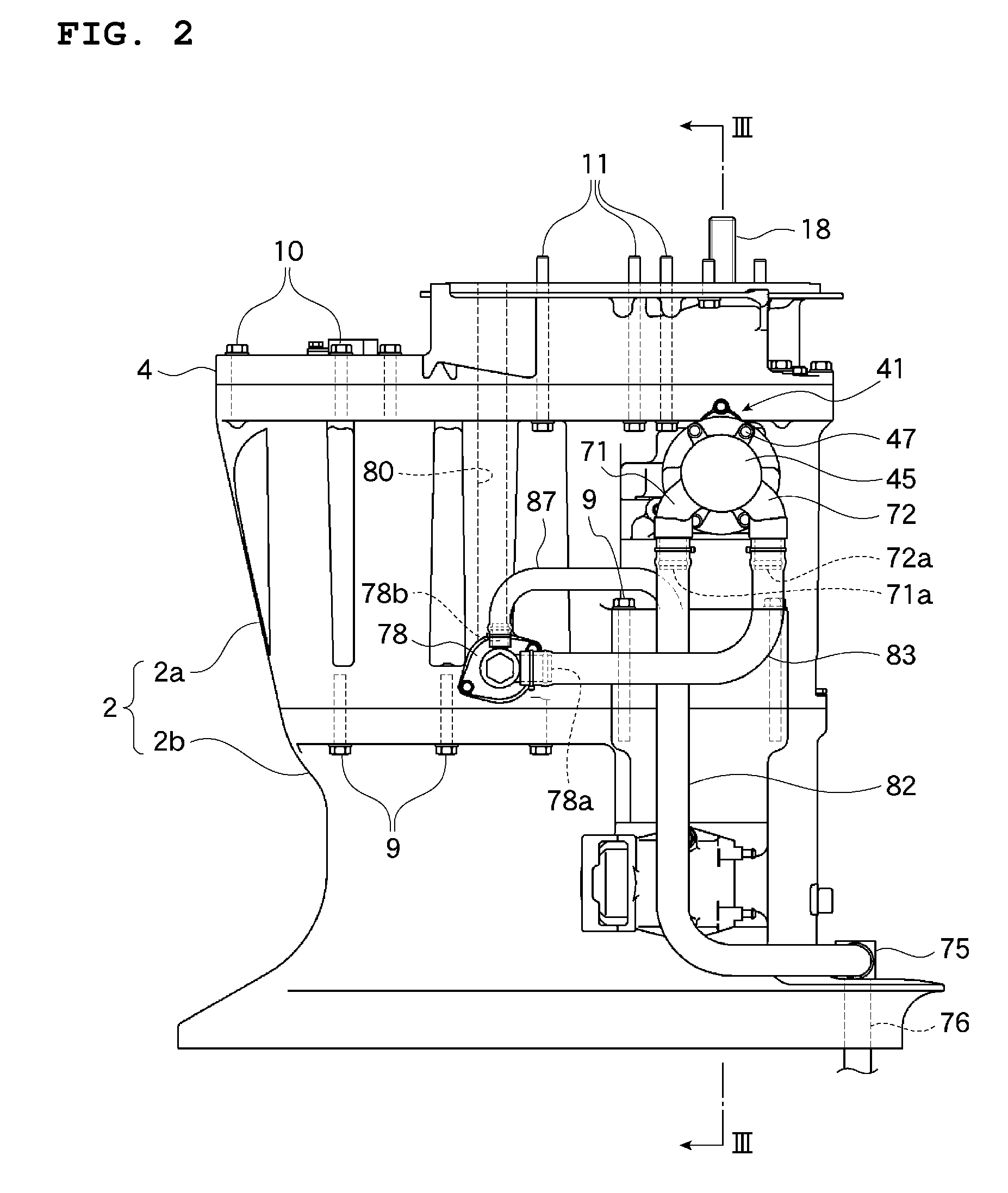
[0036]FIG. 1 is a right side view showing a preferred embodiment of an outboard motor according to the present invention. FIG. 2 is an enlarged view of a section II in FIG. 1. FIG. 3 is a vertical sectional view taken along the line III-III in FIG. 2.
[0037]In an outboard motor 1, a lower casing 3 is disposed below an upper casing 2, and an engine 5 is mounted on top of the upper casing 2 through a generally flat mounting plate 4. The engine 5 is preferably a water-cooled V6 engine, for example, and is arranged on the mounting plate 4 in a manner where a crankshaft 6 thereof extends in a vertical position.
[0038]For example, the upper casing 2 uses a horizontally split structure in which an upside casing 2a and a downside casing 2b are fastened to each other with a plurality of fixing bolts 9, for example. The mounting plate 4 can be fixed to an upper surface of ...
second preferred embodiment
[0083]Next, a second preferred embodiment of the present invention will hereinafter be described with respect to FIG. 7.
[0084]In this preferred embodiment, a pump housing 102 is fixed via a shaft housing 101 to an extension 100a that is integrally formed with a right side surface of a pump mounting case 100 (corresponding to the pump mounting case 42 in the first preferred embodiment). The shaft housing 101 and the pump housing 102 define an outer shell of the water pump 103.
[0085]The water pump 103 is driven by the rotation of the drive shaft 18 that is decelerated and then transmitted to the water pump 103 by a pump drive mechanism 105 using a bevel gear mechanism. The pump drive mechanism 105 is configured as described below.
[0086]A pump power takeoff chamber 106 is defined in the pump mounting case 100 and houses a bevel gear mechanism 107. The bevel gear mechanism 107 includes a drive bevel gear 107a and a driven bevel gear 107b. The drive bevel gear 107a is rotatably supported...
third preferred embodiment
[0093]Next, a third preferred embodiment of the present invention will hereinafter be described with respect to FIGS. 8 and 9.
[0094]In this preferred embodiment, a shaft housing 121 is fixed with a bolt 122 to an extension 120a that is integrally formed with a right side surface of a pump mounting case 120. A pump housing 123 is further fixed to an end of the shaft housing 121. The shaft housing 121 and a pump housing 123 define an outer shell of the water pump 124.
[0095]The water pump 124 is driven by the rotation of the drive shaft 18 that is decelerated and then transmitted to the water pump 124 by a pump drive mechanism 125 using a screw gear mechanism. The pump drive mechanism 125 is configured as described below.
[0096]A gearbox 126 is arranged in the pump mounting case 120 and houses a screw gear mechanism 127. The screw gear mechanism 127 includes a drive screw gear 127a and a driven screw gear 127b. The drive screw gear 127a is rotatably supported by bearings 128, 129 for un...
PUM
 Abstract
Description
Claims
Application Information