
System for displaying data relating to energy emitting treatment devices together with electrophysiological mapping data

a technology of electrophysiological mapping and treatment device, which is applied in the field of tissue treatment system and method, can solve problems such as death and variety of ailments, and achieve the effect of minimizing potential risks for patients

Inactive Publication Date: 2009-06-25
ST JUDE MEDICAL ATRIAL FIBRILLATION DIV
View PDF15 Cites 38 Cited by
  • Summary
  • Abstract
  • Description
  • Claims
  • Application Information

AI Technical Summary

Benefits of technology

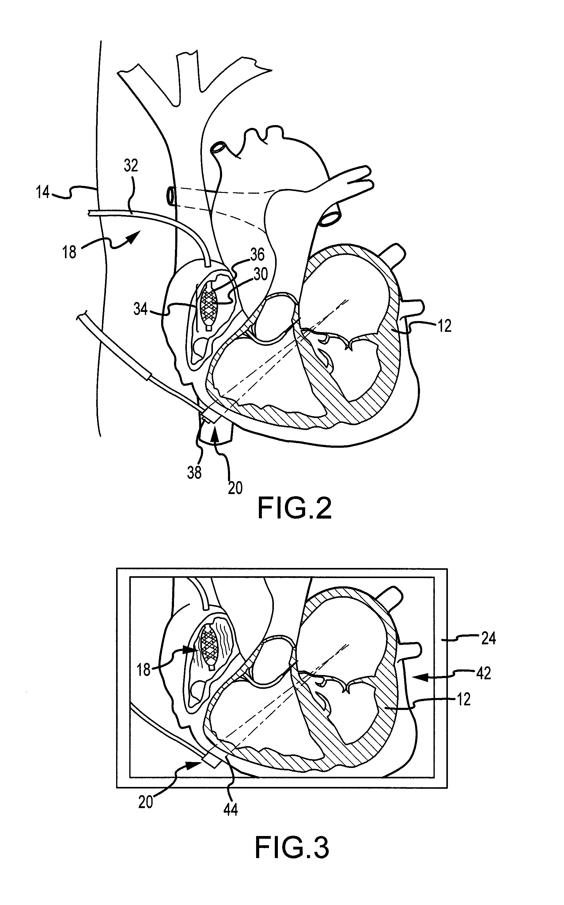
[0009]It is desirable to be able to provide information to physicians involved in the diagnosis and treatment of tissues including the position and state of the tissue and information regarding diagnostic and / or treatment devices used during diagnosis and treatment of the tissue. For example, during treatment of atrial arrhythmia, it would be useful to know not only the position of an electrophysiological mapping electrode, but also the position and orientation of a treatment device such as an ablation catheter and the ablative energy emanating from the device. This information would assist the physician in creating a lesion that is effective in treating the arrhythmia while minimizing potential risks to the patient. The inventor has therefore developed a system and method for treatment of tissue.
[0012]The above-described system and method are advantageous because they provide significant information to the physician regarding the location and orientation of the device being used to treat the tissue as well as the energy emanating from the device. Using this information, the physician can provide more effective treatment with less risk to the patient.

Problems solved by technology

Arrhythmia can create a variety of dangerous conditions including irregular heart rates, loss of synchronous atrioventricular contractions and statis of blood flow which can lead to a variety of ailments and even death.

Method used


Image

  • System for displaying data relating to energy emitting treatment devices together with electrophysiological mapping data
  • System for displaying data relating to energy emitting treatment devices together with electrophysiological mapping data
  • System for displaying data relating to energy emitting treatment devices together with electrophysiological mapping data

Examples


Embodiment Construction

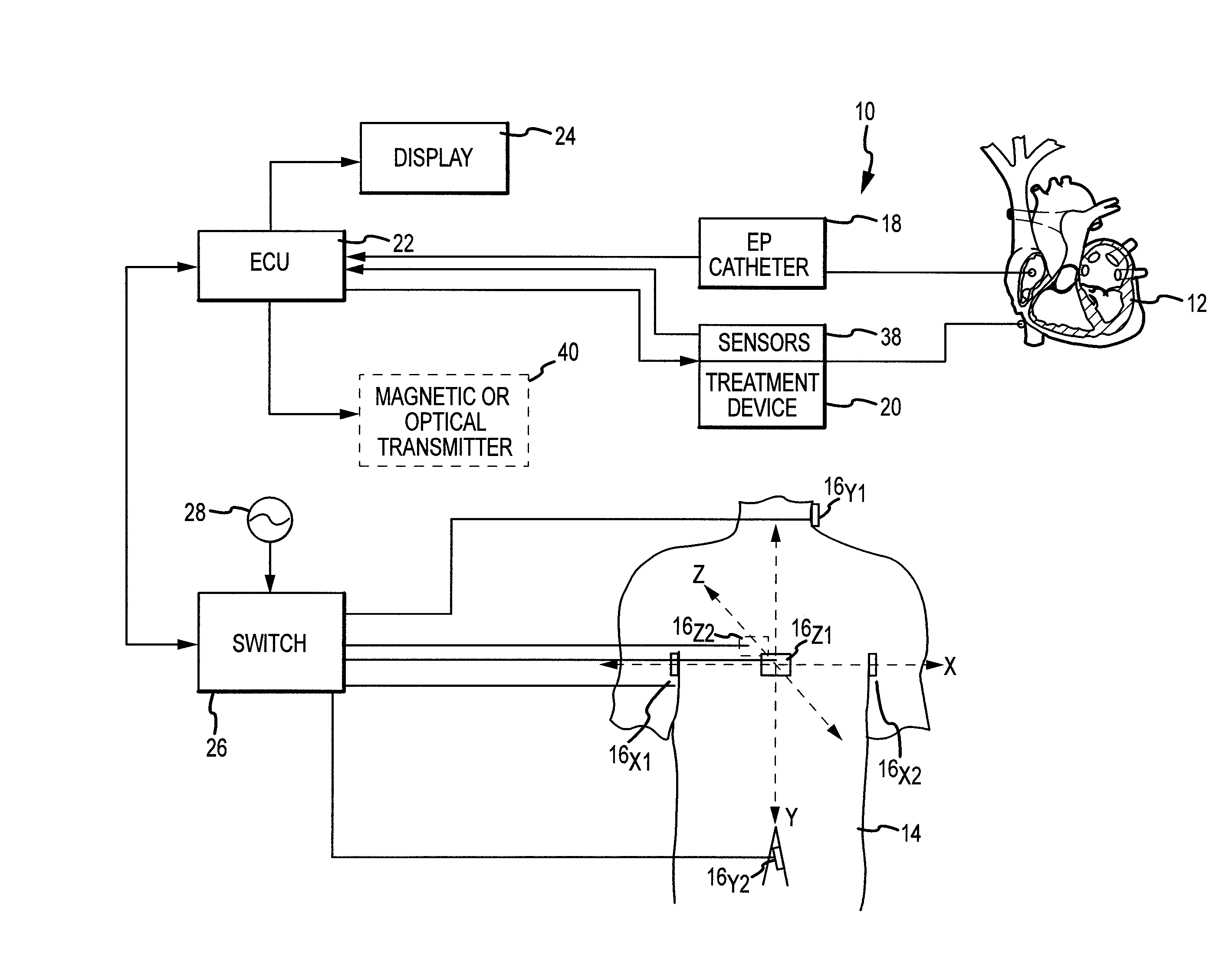
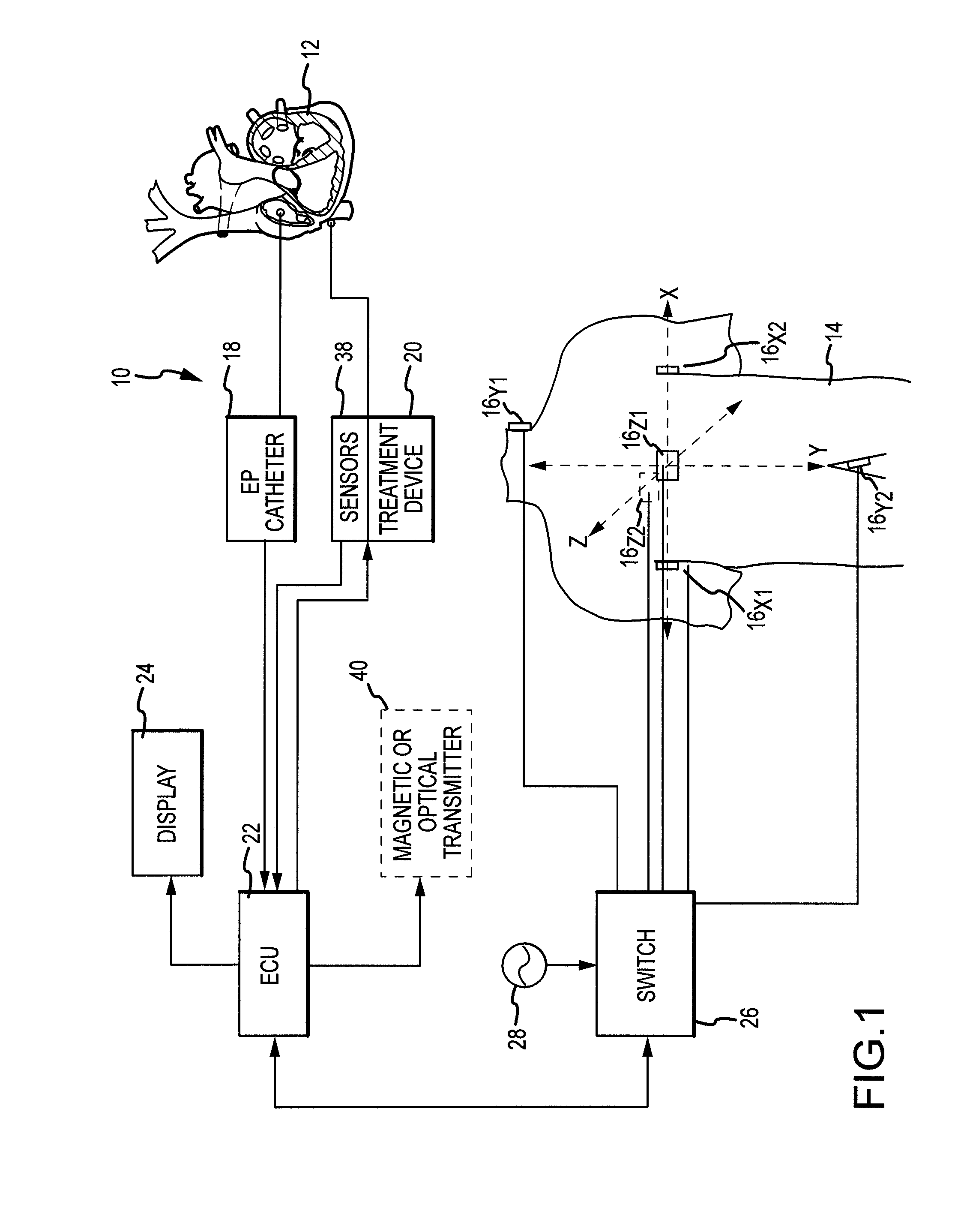
[0017]Referring now to the drawings wherein like reference numerals are used to identify identical components in the various views, FIG. 1 illustrates a system 10 for treatment of tissue 12 in a body 14. In one embodiment of the invention, tissue 12 comprises heart tissue within a human body. It should be understood, however, that the inventive system 10 may find application in connection with the treatment of a variety of tissues within human and non-human bodies. System 10 may include a plurality of patch electrodes 16 applied to body 14, an electrophysiological (EP) catheter 18, a treatment device 20, an electronic control unit (ECU) 22 and a display 24.

[0018]Patch electrodes 16 are provided to generate electrical signals used in determining the position of catheter 18 and in generating EP data regarding tissue 12. Electrodes 16 may also be used in determining the position of treatment device 20 and related information. Electrodes 16 are placed orthogonally on the surface of body...


PUM


Abstract

A system and method for treatment of tissue is provided. An electronic control unit is configured to generate displays signals used to create a graphical user interface. The display signals are generated in response to a first set of position signals indicative of the position of an electrophysiology mapping electrode relative to the tissue and a second set of position signals indicative of the position of a treatment device, such as a high intensity focused ultrasound transducer, that is configured to generate a beam of energy towards a selected region in the tissue. The graphical user interface displays an electrophysiology map of the tissue and an image of at least one of the treatment device and the beam of energy which may be superimposed on the electrophysiology map.

Description

BACKGROUND OF THE INVENTION[0001]a. Field of the Invention[0002]The instant invention relates to a system and method for treatment of tissue. In particular, the instant invention relates to a system and method in which at least one of a treatment device and a beam of energy generated by the treatment device during treating of tissue is displayed together with electrophysiological mapping data.[0003]b. Background Art[0004]The use of electrophysiological (EP) mapping data in the diagnosis and treatment of tissues within a body is well known. In a conventional system, a catheter may be inserted within a vessel located near the surface of a body (e.g., in an artery or vein in the leg, neck, or arm) and maneuvered to a region of interest within the body. An electrode disposed at one end of the catheter detects changes in electrical potential resulting from the transmission of electrical signals between points on the body. Signals generated by the electrode are then used to generate an im...

Claims


Application Information

Patent Timeline
IPC IPC(8): A61B5/05
CPCA61B5/042A61B5/044A61N7/02A61B19/56A61B19/5244A61B34/20A61B34/25A61B5/283A61B5/339
Inventor SLIWA, JOHN W.
Owner ST JUDE MEDICAL ATRIAL FIBRILLATION DIV
Learn More