
Exhaust Gas Analysis Method and Exhaust Gas Analysis Apparatus

Inactive Publication Date: 2009-06-25
TOYOTA JIDOSHA KK +1
View PDF13 Cites 37 Cited by
  • Summary
  • Abstract
  • Description
  • Claims
  • Application Information

AI Technical Summary

Benefits of technology

[0007]The present invention has been made in view of such a problem. An object of the present invention is to provide an exhaust gas analysis method and an exhaust gas analysis apparatus substantially insensitive to variation in pressure and temperature of the exhaust gas and capable of calculating, measuring, and analyzing the concentration of any of the components contained in the exhaust gas in an accurate, real-time manner.
[0020]According to the exhaust gas analysis method and the exhaust gas analysis apparatus of the present invention, when the exhaust gas is analyzed by sending the laser beam through the exhaust gas and using the absorption spectrum of the laser beam that has passed through the exhaust gas to calculate the gas concentration of a specific component in the exhaust gas, temperature-dependent and pressure-dependent errors in the calculated gas concentration can be corrected in real-time. As a result, an accurate gas concentration value can be calculated, measured, and analyzed. Further, since the shape of the absorption spectrum is used to calculate the pressure in the pressure detection process, no pressure gauge is necessary, so that the apparatus configuration can be simplified and the pressure measurement can be performed quickly.

Problems solved by technology

In this case, however, the system becomes complicated partly because the number of parts increases.
In this process, the calculation for determining the concentration using the shape of the absorption spectrum as a parameter requires repetitive calculation, resulting in increase in analysis time and hence difficulty performing real-time measurement.

Method used


Image

  • Exhaust Gas Analysis Method and Exhaust Gas Analysis Apparatus
  • Exhaust Gas Analysis Method and Exhaust Gas Analysis Apparatus
  • Exhaust Gas Analysis Method and Exhaust Gas Analysis Apparatus

Examples


Embodiment Construction

[0036]An embodiment in which the gas analysis apparatus according to the present invention is applied to an exhaust gas analysis apparatus for an automobile will be described below in detail with reference to the drawings.

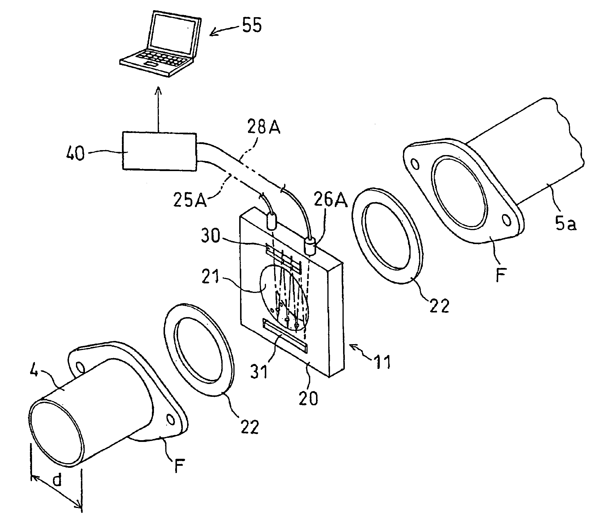
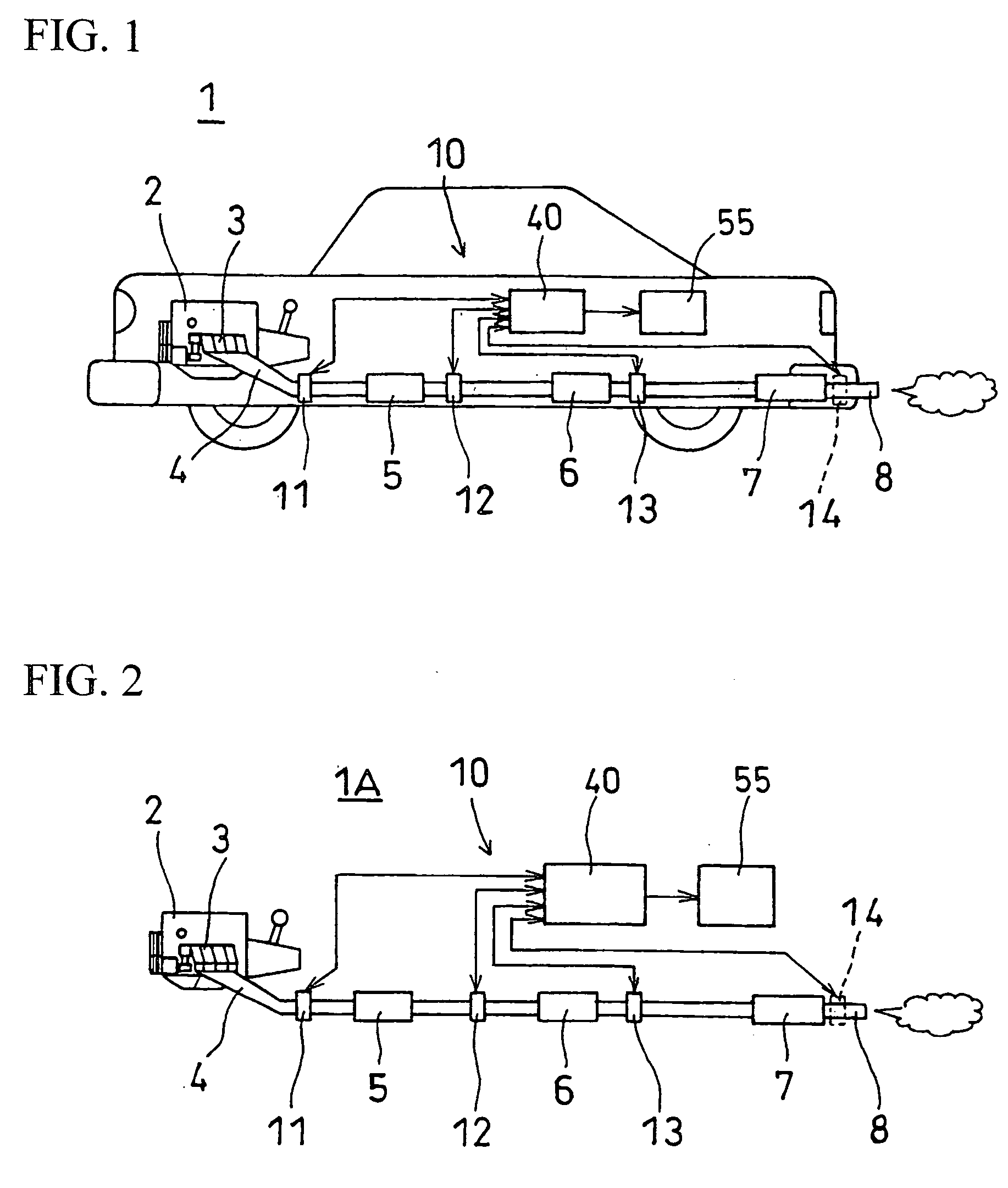
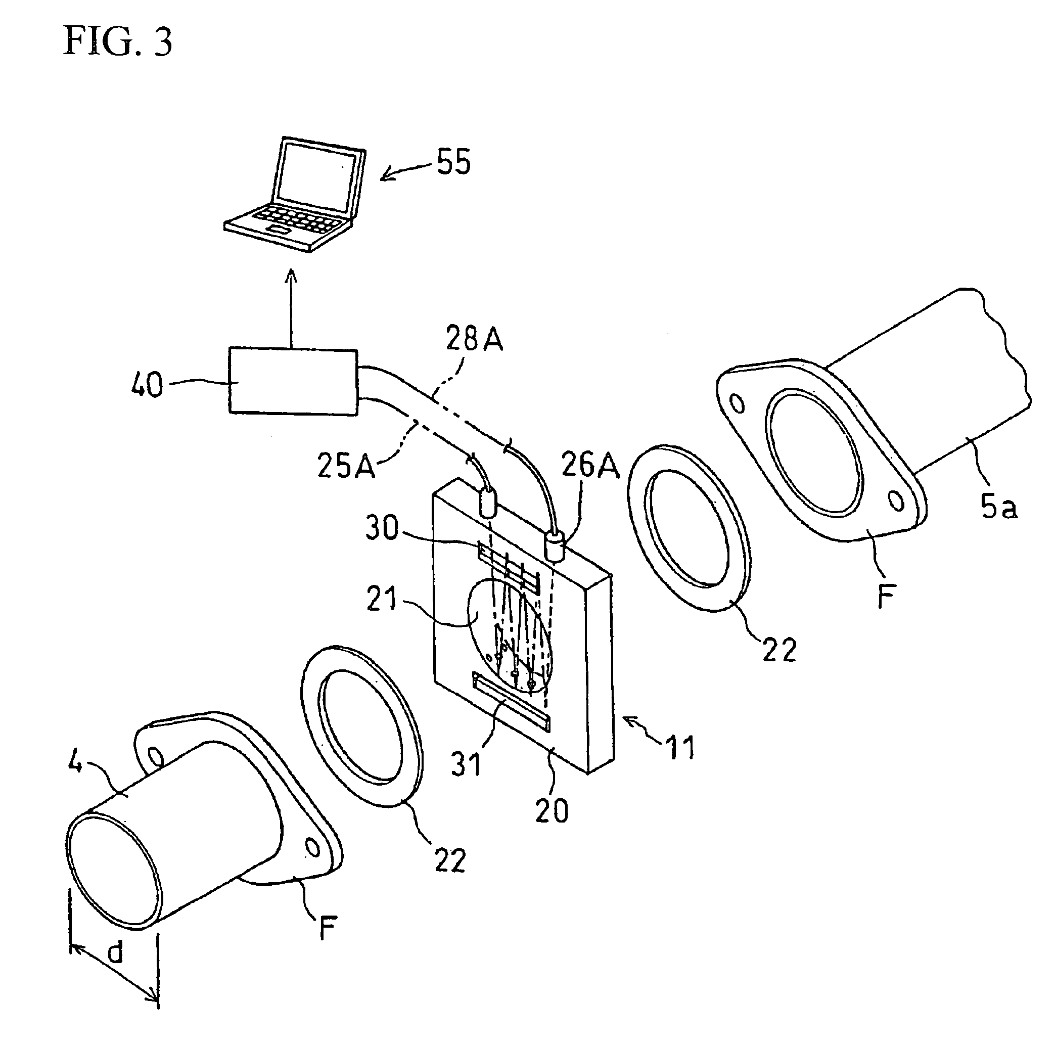
[0037]FIG. 1 is a key component configuration diagram of the exhaust gas analysis apparatus according to the present invention implemented in an automobile. FIG. 2 is a key component configuration diagram of the exhaust gas analysis apparatus in FIG. 1 mounted on an engine bench. FIG. 3 is a key component configuration diagram of the exhaust gas analysis apparatus, including an exploded perspective view of the key components of a sensor unit. FIGS. 4(a) to 4(d) are a partial cross-sectional front view showing the details of the sensor unit in FIG. 3, the cross-sectional view taken along the line A-A, the cross-sectional view taken along the line B-B, and the key component cross-sectional view taken along the line C-C, respectively. FIG. 5 is a block diagram showing...


PUM


Abstract

An exhaust gas analysis method comprises applying a laser beam to the exhaust gas discharged from an internal combustion engine, receiving the laser beam that has passed through the exhaust gas, and measuring the concentration of any of the components contained in the exhaust gas based on the received laser beam. The exhaust gas analysis method further comprises detecting the absorption spectrum of the laser beam absorbed in the exhaust gas by using the received laser beam (S1), calculating the concentration of the specific gas component by using the absorption spectrum (S2), calculating the temperature of the exhaust gas by using the absorption spectrum (S3), calculating the pressure of the exhaust gas by using the absorption spectrum (S4 to S6), correcting the calculated concentration of the component contained in the exhaust gas by using the calculated temperature (S7), correcting the concentration by using the calculated pressure (S8), and outputting the true concentration value (S9). Accordingly, the exhaust gas analysis method is substantially insensitive to variation in pressure and temperature of the exhaust gas and capable of calculating and analyzing the concentration of any of the components contained in the exhaust gas in an accurate, realtime manner.

Description

TECHNICAL FIELD[0001]The present invention relates to a method for analyzing an exhaust gas discharged from an internal combustion engine of an automobile or the like and an exhaust gas analysis apparatus, and particularly to an exhaust gas analysis method and an exhaust gas analysis apparatus for calculating, measuring, and analyzing the concentrations, temperatures, and the like of the components contained in an exhaust gas in an accurate, real-time manner.BACKGROUND ART[0002]As a conventional exhaust gas analysis apparatus of this type, Patent Document 1 discloses an in-vehicle HC measurement apparatus. The in-vehicle HC measurement apparatus includes the following in-vehicle components: an NDIR (non-dispersive infrared spectroscopy) gas analyzer for continuously measuring the HC (hydrocarbon) concentration in the exhaust gas flowing through the exhaust duct connected to the engine, an exhaust gas flowmeter for continuously measuring the flow of the exhaust gas flowing through th...

Claims


Application Information

Patent Timeline
IPC IPC(8): G01N21/31G06F19/00F02D45/00G01N21/3504G01N21/35G01N21/359
CPCG01N21/031G01N21/3504G01N21/314G01N21/25
Inventor GOTO, KATSUTOSHIYAMAKAGE, MASAHIROIWASE, TOMOYASUOKANO, TOKIODEGUCHI, YOSHIHIROMIZOGUCHI, MASANOBUTAKITA, ATUSHIFUKUDA, NORIHIRO
Owner TOYOTA JIDOSHA KK
Learn More