Grounding switch

a grounding switch and switch technology, applied in the field of grounding switches, can solve the problems of gas that has increased in temperature not cooling, arc occurs due, and further repulsive force is exerted on the moving conta

Active Publication Date: 2009-07-02
MITSUBISHI ELECTRIC CORP
View PDF4 Cites 27 Cited by
  • Summary
  • Abstract
  • Description
  • Claims
  • Application Information

AI Technical Summary

Benefits of technology

[0007]It is an object of the present invention to at least

Problems solved by technology

This is to say that if the moving contact erroneously enters into the high-voltage electrode in a state where a high voltage is applied, an arc occurs due to breakdown of insulation between the electrodes.
When operation of the moving contact continues so that the high-voltage arc contact and the moving arc contact make contact, frictional resistance occurs between the electrodes and there is further repulsive force exerted on the moving contact.
However, gas that has increased in temperature does not

Method used


Image

  • Grounding switch
  • Grounding switch
  • Grounding switch

Examples


Embodiment Construction

[0020]Exemplary embodiments of a grounding switch of the present invention are explained in detail with reference to the drawings. The invention is by no means limited to the embodiments.

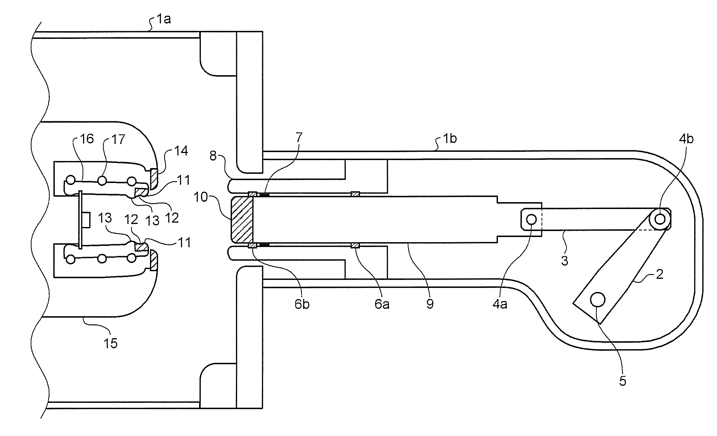
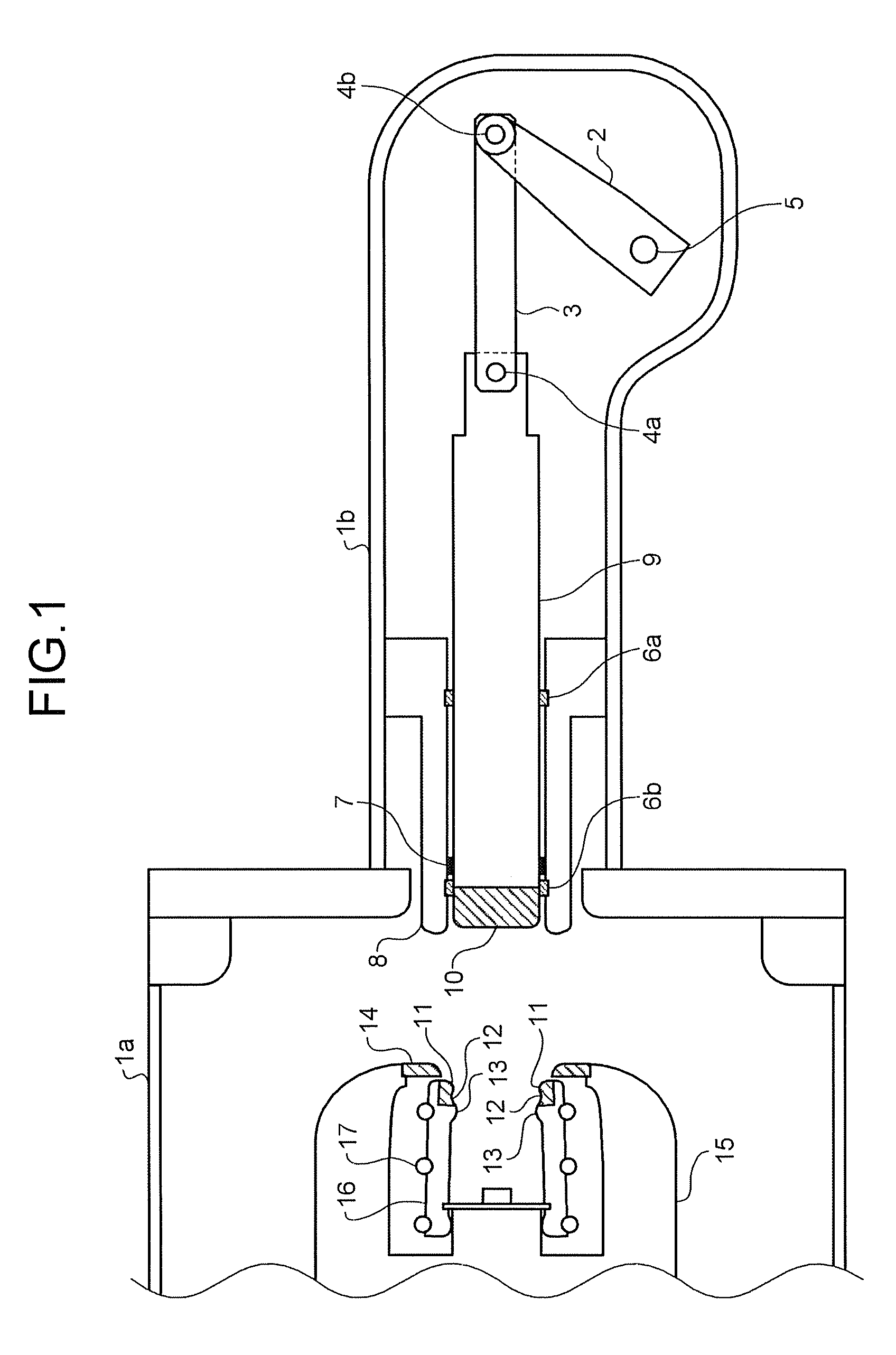
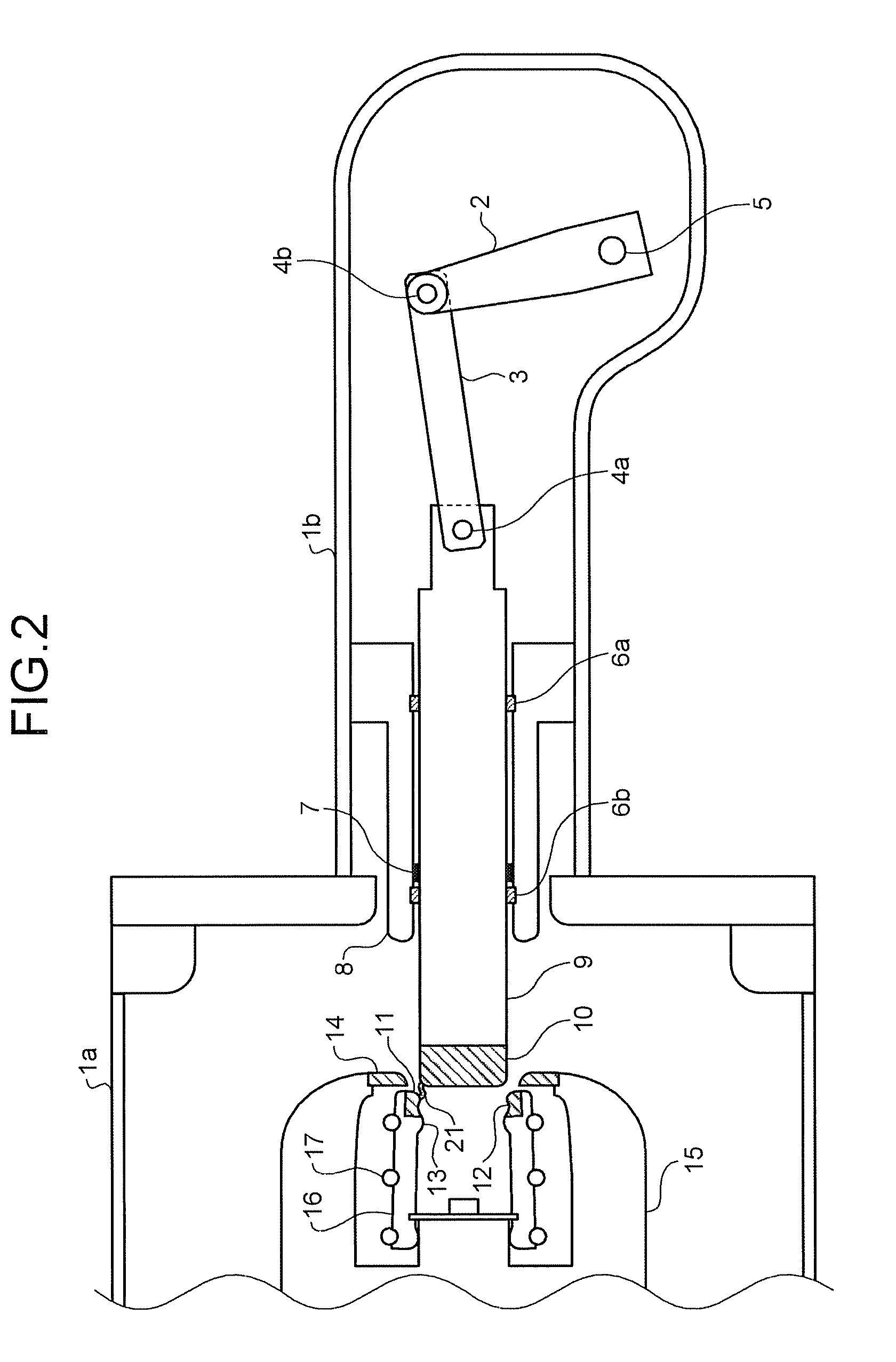
[0021]FIG. 1 is a cross-section of an open state of a grounding switch according to a first embodiment of the present invention. FIG. 2 is a cross-section of a situation where an arc occurs across a high-voltage arc contact and a moving arc contact when the grounding switch of FIG. 1 is midway through going from an open state to a closed state. FIG. 3 is a cross-section of a situation where the moving arc contact and the high-voltage arc contact make contact when the grounding switch of FIG. 1 is midway through going from an open state to a closed state. FIG. 4 is a cross-section of a closed state of the grounding switch of FIG. 1. In the grounding switch of the first embodiment, a high-voltage electrode 15 and an earth electrode 8 are housed in a tank 1a and a tank 1b, respectively, that encapsulat...


PUM


Abstract

A valley section is provided between a high-voltage arc contact and a high-voltage main contact. Because of the presence of the valley section, resistance between contacts is reduced while a moving arc contact makes contact with the high-voltage arc contact and then slides up to making contact with the high-voltage main contact.

Description

BACKGROUND OF THE INVENTION[0001]1. Field of the Invention[0002]The present invention relates to a grounding switch that is incorporated in gas insulated switchgear.[0003]2. Description of the Related Art[0004]A grounding switch is incorporated in gas insulated switchgear (GIS). The grounding switch is used as a contact in grounding of a main circuit when testing equipment, or as an earth terminal when measuring equipment. When grounding a main circuit, typically, a moving contact, which is grounded, is moved along a center axis of the grounding switch so as to be inserted into a high-voltage electrode, which is connected to high voltage. If, by any possibility, the moving contact moves in an axial direction of the grounding switch and is inserted into a high-voltage electrode as the result of an erroneous operation when high voltage is being applied to the main circuit, there has been a need of a function which is capable of opening the grounding switch afterwards with a reliable e...

Claims


Application Information

Patent Timeline
IPC IPC(8): H01H31/02
CPCH01H33/901H01H31/003
Inventor NAKAUCHI, SHINICHIROSHIMIZU, YOSHINORI
Owner MITSUBISHI ELECTRIC CORP
Why Eureka
Try Eureka