Imaging device

a technology of imaging device and camera, which is applied in the field of imaging device, can solve the problems of unfavorable special care and trouble, and achieve the effect of improving the usability of imaging devi

Inactive Publication Date: 2009-07-02
ELMO CO LTD
View PDF5 Cites 4 Cited by
  • Summary
  • Abstract
  • Description
  • Claims
  • Application Information

AI Technical Summary

Benefits of technology

[0018]In the imaging device of this application, the command operation unit may have the three image selection switches and the another operation switch arranged to surround the menu switch. Such concentration of the switches desirably improves the usability of the imaging device.
[0019]In still another preferable application of the imaging device, the command display module displays the menu image in a hierarchical manner. A top menu image displayed by the command display module on an uppermost layer in the hierarchy includes a command icon specifying display of a camera image taken with the camera unit to the display unit and output of the camera image to the external display device, a command icon specifying display of an external input image from an external image output device to the display unit and output of the external input image to the external display device, a command icon specifying display of a read image from a storage medium used for storage of the image to the display unit and output of the read image to the external display device, and a command icon specifying a switchover of an on-off condition of a lighting unit, which is used to illuminate an imaging object placed on a table of the imaging device. The imaging de...

Problems solved by technology

This undesirably takes the special care and trouble of keeping a...

Method used


Image

  • Imaging device
  • Imaging device
  • Imaging device

Examples


Embodiment Construction

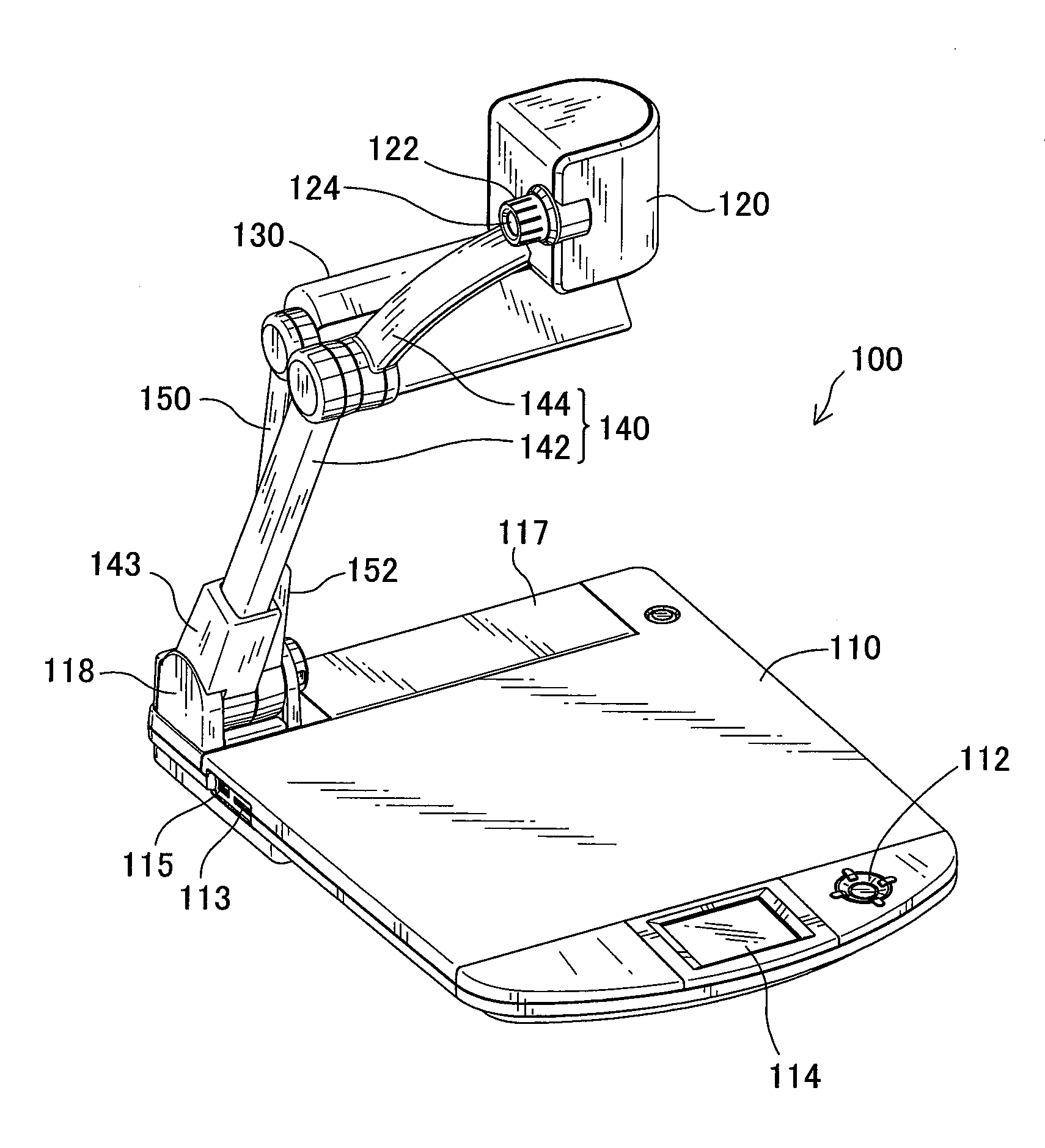
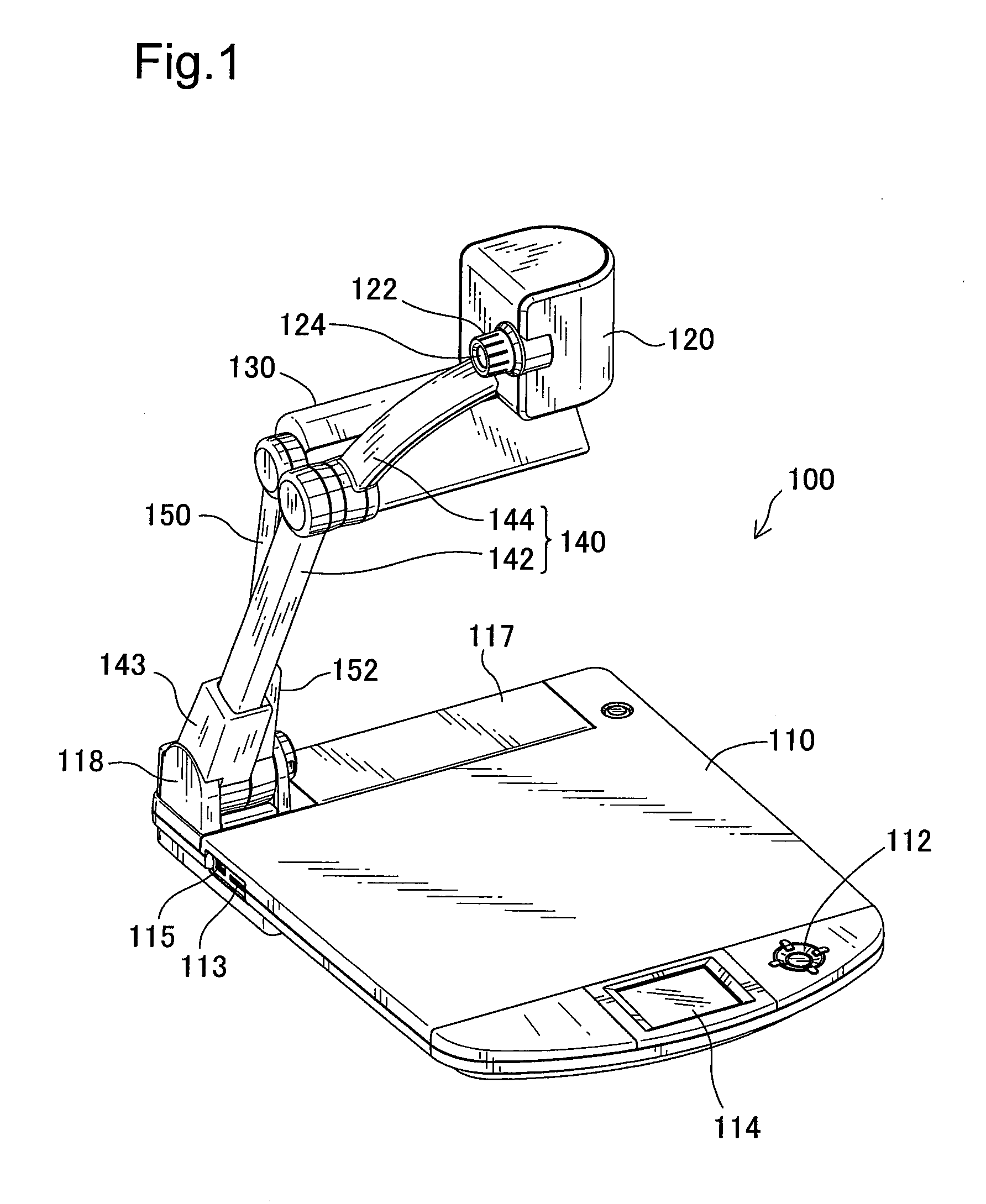
[0040]One mode of carrying out the invention is described below as a preferred embodiment with reference to the accompanied drawings. FIG. 1 is a perspective view showing an imaging device 100 in one embodiment of the invention.

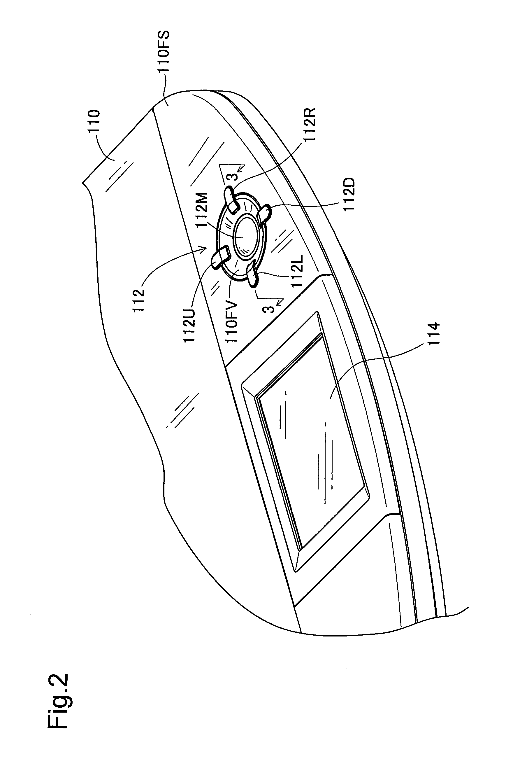
[0041]As illustrated, the imaging device 100 includes a table 110 designed to enable an imaging object (not shown) to be placed thereon, a camera head 120 used to take an image of the imaging object placed on the table 110, and a lighting unit 130 designed to illuminate the imaging object placed on the table 110. The table 110 is a plate in a rectangular shape having rounded front corners and has an inclined surface 110FS formed on the front side of the top face of the table 110. The inclined surface 110FS has a switch assembly 112 and a monitor 114. A memory card insertion mechanism 113 and a USB (universal serial bus) terminal 115 are provided on a left rear side wall of the table 110. The switch assembly 112 has multiple switches for setting illumination o...


PUM


Abstract

This attempts to reduce the total number of physical operation switches while simplifying device settings based on commands.
In a command setting mode where a composite image of a menu image with a source image as a background is displayed on a monitor 114, a menu switch 112M functions to set a selected command icon. An up switch 112U and other circumferential switches surrounding the menu switch 112M function to select one of multiple command icons included in the menu image. In a mode other than the command setting mode, the circumferential switches function as physical operation switches to change over an on-off condition of a lighting unit and to select an image input source. This arrangement desirably reduces the total number of physical operation switches, while simplifying the device settings based on commands.

Description

CROSS-REFERENCE TO RELATED APPLICATIONS[0001]The present application claims the priority based on Japanese Patent Application No. 2007-339791 filed on December 28, 2007, the disclosure of which is hereby incorporated by reference in its entirety.BACKGROUND[0002]1. Technical Field[0003]The present invention relates to an imaging device configured to take an image in a predetermined imaging area with a camera unit and displaying the camera-taken image on a display unit.[0004]2. Related Art[0005]In general application of imaging devices, an image in a predetermined imaging area, for example, an imaging object placed on a table, is taken with an internal camera of a camera unit and is displayed on a display unit. This application enables the user of the imaging device to give a presentation, while conveniently checking the conditions of the camera-taken image. One proposed technique for the imaging device sets various working conditions of the imaging device, for example, brightness adj...

Claims


Application Information

Patent Timeline
IPC IPC(8): H04N5/225
CPCG06F3/0346G06F3/0425H04N1/00387H04N1/00408H04N1/00416H04N1/00424H04N2201/0436H04N1/00453H04N1/00482H04N1/195H04N1/19594H04N5/23216H04N1/0044H04N23/62H04N23/60
Inventor UEDA, TAKENORINAKAYAMA, YOSHIHIKOKATO, TETSUROKAJIMA, NAOKO
Owner ELMO CO LTD
Why Eureka
Try Eureka