Zoom lens

Inactive Publication Date: 2009-07-02
FOXSEMICON INTEGRATED TECH INC
View PDF3 Cites 548 Cited by
  • Summary
  • Abstract
  • Description
  • Claims
  • Application Information

AI Technical Summary

Problems solved by technology

However, zooming function is accomplished by moving lenses along the optical axis of a zoom lens unit, which requires a significant amount of space, thus further reduction in size of the phone is difficult.

Method used


Image

  • Zoom lens
  • Zoom lens
  • Zoom lens

Examples


Embodiment Construction

[0011]Reference will now be made to the drawings to describe the embodiments of the present zoom lens, in detail.

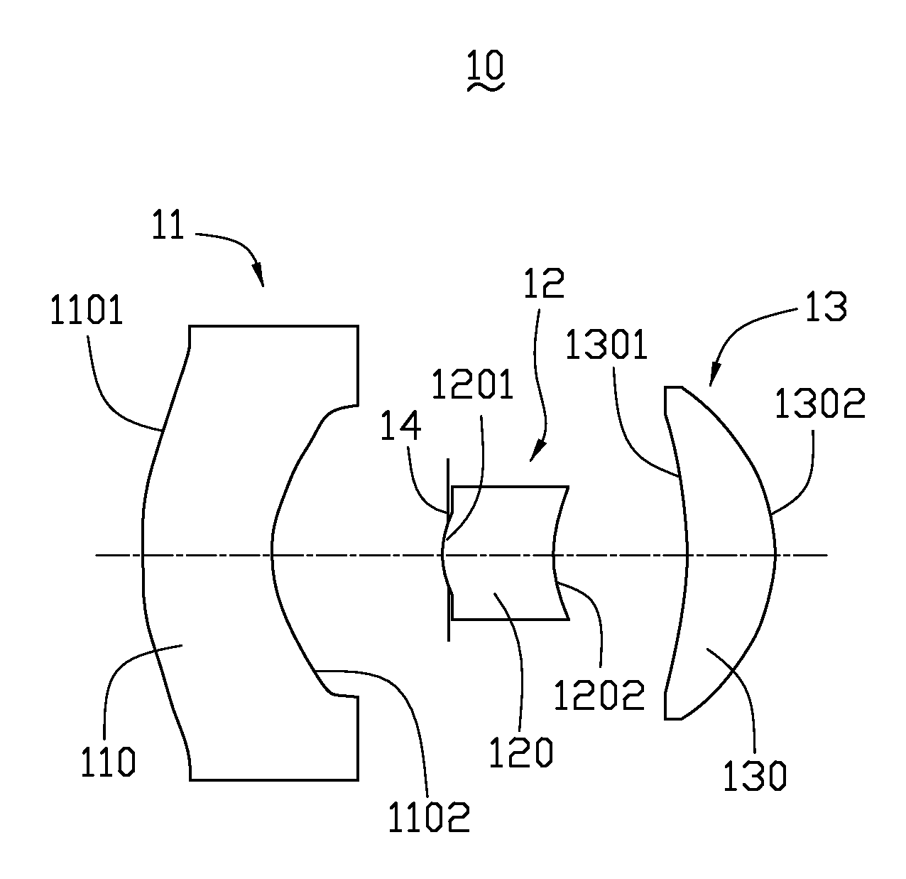
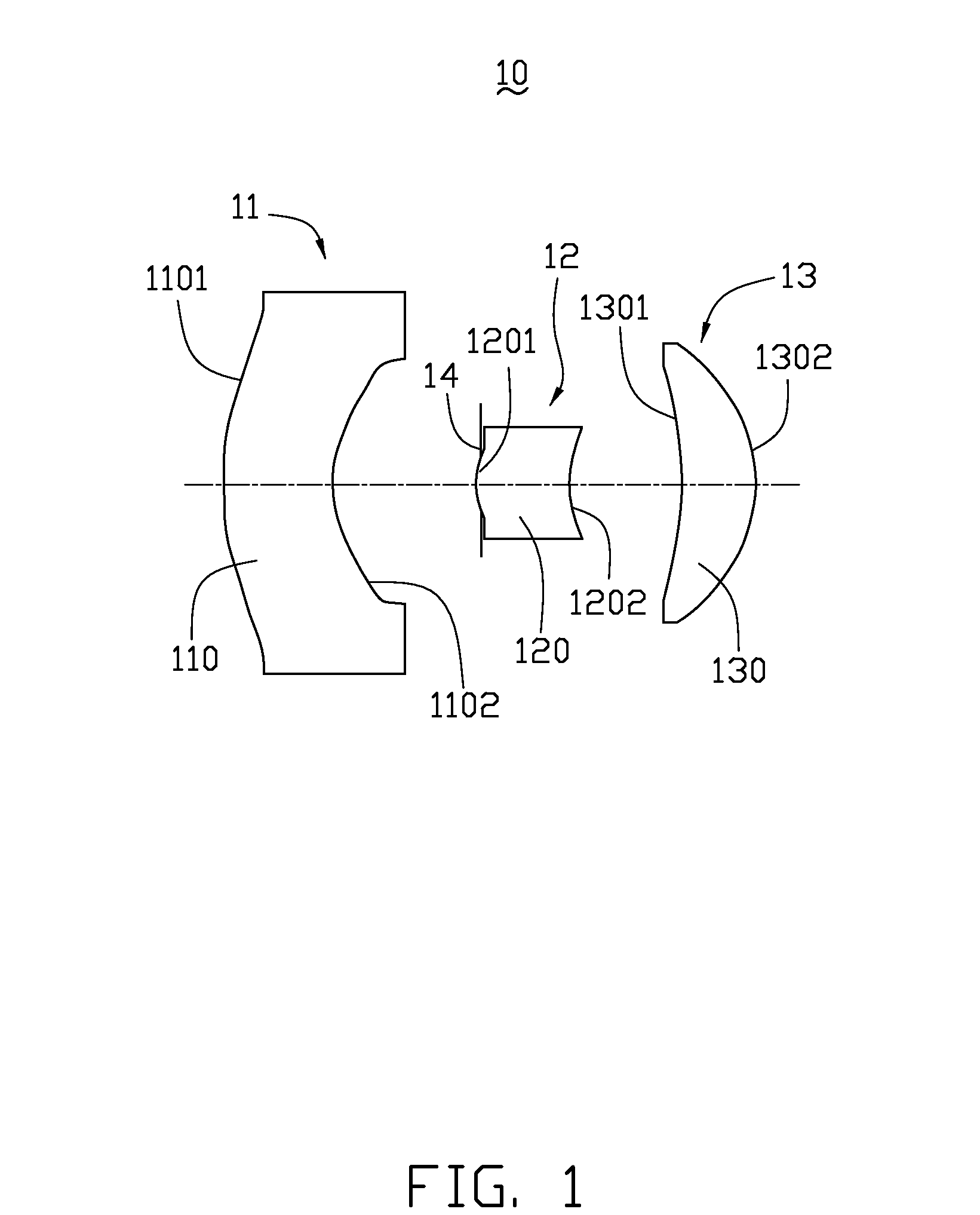
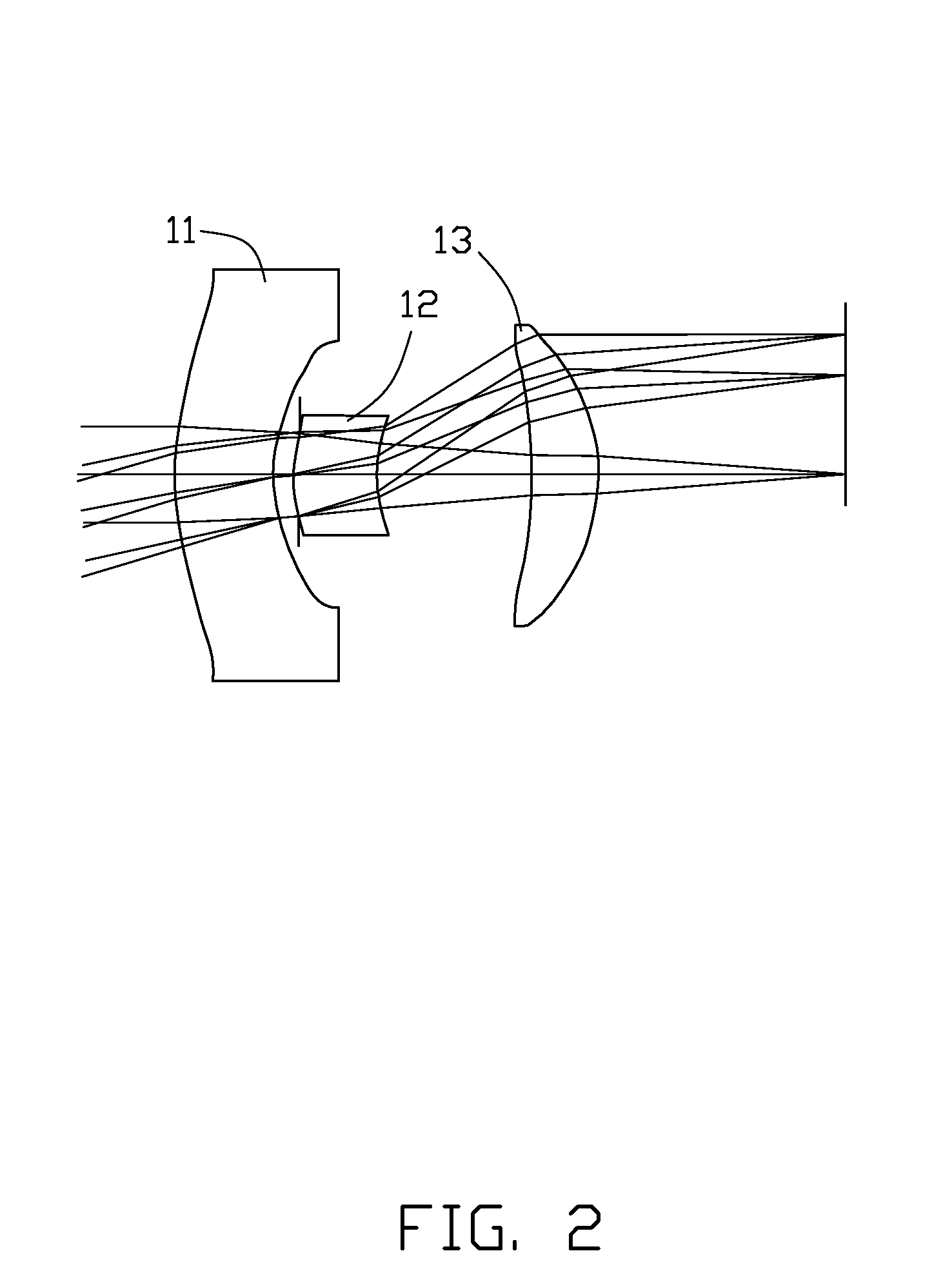
[0012]Referring to FIG. 1, a zoom lens 10 according to a first exemplary embodiment is provided. The zoom lens 10 includes, from an object side of the zoom lens, a first lens module 11 having a negative refractive power, a second lens module 12 having a positive refractive power and a third lens module 13 having a positive refractive power.

[0013]The first lens module 11 remain still when the zoom lens 10 is adjusted from wide-angle to telephoto. The first lens module 11 includes a lens 110 having negative refractive power. The first lens module 11 is configured for receiving light from an object. The lens 110 includes two surfaces 1101, 1102. At least one of the surfaces 1101, 1102 is an aspherical surface. The lens 110 can be a polymer lens or a glass lens.

[0014]The second lens module 12 is capable of being moved toward the object side along an optical axis of the zoom l...


PUM


Abstract

An exemplary zoom lens comprises, in order from an object side of the zoom lens, a first lens module having a negative refractive power, a second lens module having a positive refractive power and a third lens module having a positive refractive power. When the zoom lens is adjusted from wide-angle to telephoto, the first lens module remain fixed in place, the second group is moved toward the object side thereof along an optical axis so as to perform the zooming, while the third group is moved along the optical axis so as to compensate for any fluctuation of in position of an image on the image plane caused by the movement of the second lens module.

Description

BACKGROUND[0001]1. Technical Field[0002]The present invention generally relates to zoom lenses, particularly, to a zoom lens with compact configuration.[0003]2. Discussion of Related Art[0004]Mobile telephones equipped with cameras having a solid-state image sensor, such as charge couple device (CCD), are very popular. Such mobile phones typically include zoom lenses allowing users to have greater versatility in picture taking. However, zooming function is accomplished by moving lenses along the optical axis of a zoom lens unit, which requires a significant amount of space, thus further reduction in size of the phone is difficult.[0005]Therefore, what is needed is a zoom lens that has a compact configuration.BRIEF DESCRIPTION OF THE DRAWINGS[0006]Many aspects of the present zoom lens can be better understood with reference to the following drawings. The components in the drawings are not necessarily drawn to scale, the emphasis instead being placed upon clearly illustrating the prin...

Claims


Application Information

Patent Timeline
IPC IPC(8): G02B15/14
CPCG02B13/0035G02B15/177G02B13/009G02B15/143507
Inventor HUNG, CHAO-YUCHERN, JYH-LONG
Owner FOXSEMICON INTEGRATED TECH INC
Why Eureka
Try Eureka