Substrate for Use in Metrology, Metrology Method and Device Manufacturing Method

a metrology and substrate technology, applied in the direction of material analysis, printing, instruments, etc., can solve the problems of increasing the space on the substrate and inability to provide product features, and achieve the effect of reducing the space occupied

Inactive Publication Date: 2012-02-23
ASML NETHERLANDS BV
View PDF2 Cites 1011 Cited by
  • Summary
  • Abstract
  • Description
  • Claims
  • Application Information

AI Technical Summary

Benefits of technology

[0012]In one example, the elongated form of a grating having such an aspect ratio allows the occupied area to be reduced while mitigating one or more of the problems associated with shrinking the grating. The aspect ratio of the individual grating portion may be greater than 1.5. The aspect ratio may be substantially an integer, for example 2, 3 or 4, so that gratings with X and Y orientation can be packed efficiently into a rectangular target area.

Problems solved by technology

The use of multiple pairs of gratings also increases the space on the substrate that needs to be devoted to metrology targets and hence is unavailable for product features.
1. Edge effects due to the visibility of the grating edges within the illumination spot may become important, even when using dark field techniques.
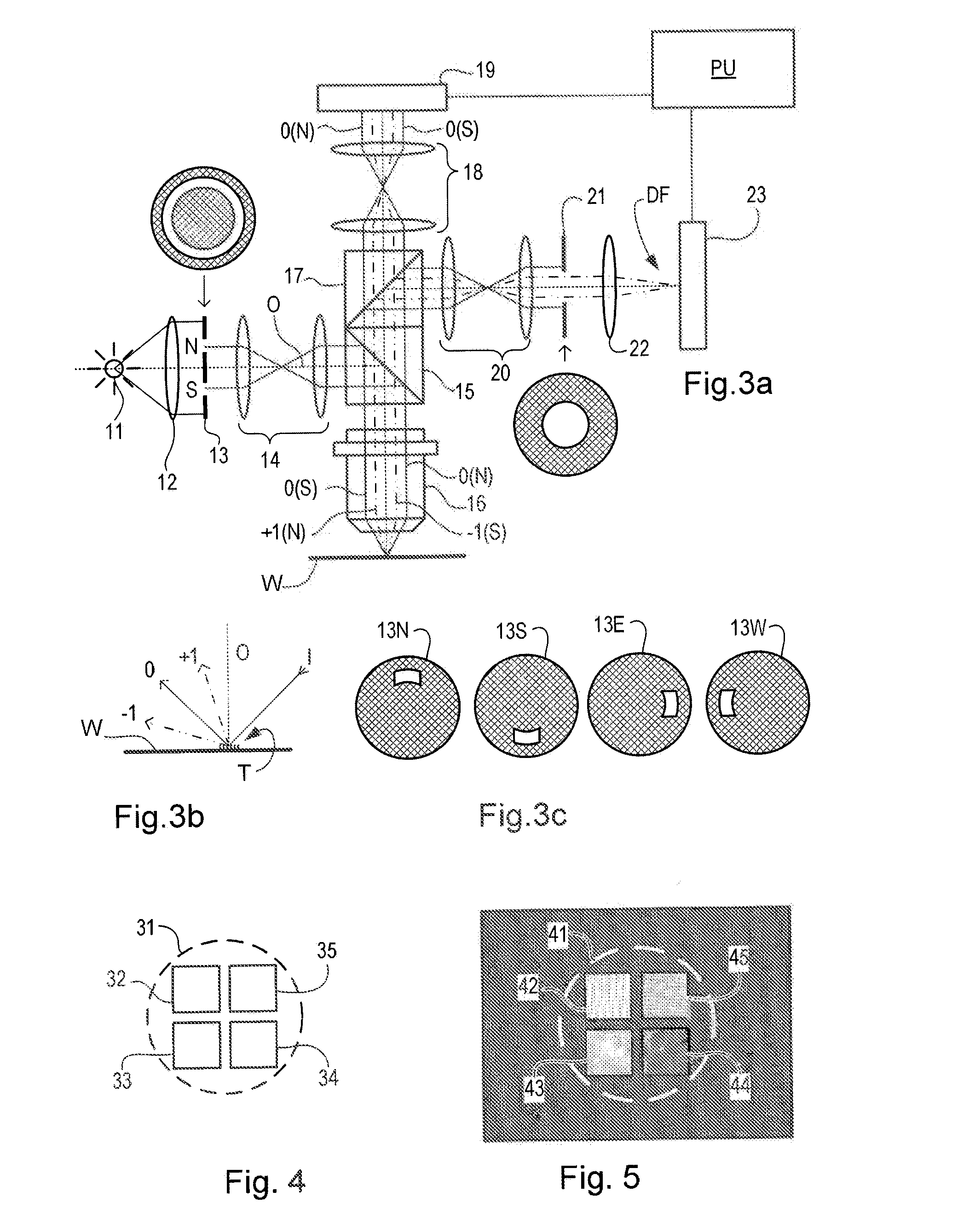
2. The point-spread-function at the level of the pupil plane is no longer determined only by the illumination spot shape and size, but becomes dominated by the grating size and shape. This will cause undesired interference (smearing) between corresponding coherent pupil plane points of the different diffraction orders. The problem of the point spread function is discussed in international patent application WO 2010 / 025950 A1, which is incorporated by reference herein in its entirety. There it is proposed to put the grating lines at an angle (e.g., 45 degrees) to the illumination / detection direction, so that smeared orders are further apart.
3. For diffraction into discrete orders, one should have a repeating unit (in one or more directions). This is formed by the lines that repeat with a frequency defined by the grating pitch. If the target is made smaller and the pitch is large (e.g., about 1000 nm), then the number of lines to form a repeating structure become fewer. Sometimes it is desired to make so-called “interlaced” gratings that have lines of two different exposures non-overlapping in the same layer. The pitch of such case is rather large, such that for a 4×4 μm2 grating only maximum four lines can be admitted for each exposure. This is barely sufficient to consider a repeating unit.

Method used


Image

  • Substrate for Use in Metrology, Metrology Method and Device Manufacturing Method
  • Substrate for Use in Metrology, Metrology Method and Device Manufacturing Method
  • Substrate for Use in Metrology, Metrology Method and Device Manufacturing Method

Examples


Embodiment Construction

[0031]This specification discloses one or more embodiments that incorporate the features of this invention. The disclosed embodiment(s) merely exemplify the invention. The scope of the invention is not limited to the disclosed embodiment(s). The invention is defined by the claims appended hereto.

[0032]The embodiment(s) described, and references in the specification to “one embodiment”, “an embodiment”, “an example embodiment”, etc., indicate that the embodiment(s) described may include a particular feature, structure, or characteristic, but every embodiment may not necessarily include the particular feature, structure, or characteristic. Moreover, such phrases are not necessarily referring to the same embodiment. Further, when a particular feature, structure, or characteristic is described in connection with an embodiment, it is understood that it is within the knowledge of one skilled in the art to effect such feature, structure, or characteristic in connection with other embodimen...


PUM

PropertyMeasurementUnit
aspect ratioaaaaaaaaaa
widthaaaaaaaaaa
widthaaaaaaaaaa

Abstract

A pattern from a patterning device is applied to a substrate. The applied pattern includes device functional areas and metrology target areas. Each metrology target area comprises a plurality of individual grating portions, which are used for diffraction based overlay measurements or other diffraction based measurements. The gratings are of the small target type, which is small than an illumination spot used in the metrology. Each grating has an aspect ratio substantially greater than 1, meaning that a length in a direction perpendicular to the grating lines which is substantially greater than a width of the grating. Total target area can be reduced without loss of performance in the diffraction based metrology. A composite target can comprise a plurality of individual grating portions of different overlay biases. Using integer aspect ratios such as 2:1 or 4:1, grating portions of different directions can be packed efficiently into rectangular composite target areas.

Description

CROSS REFERENCE TO RELATED APPLICATIONS[0001]This application claims benefit under 35 U.S.C. §119(e) to U.S. Provisional Application No. 61 / 374,766, filed Aug. 18, 2011, which is incorporated by reference herein in its entirety.BACKGROUND[0002]1. Field of the Present Invention[0003]The present invention relates to methods and apparatus for metrology usable, for example, in the manufacture of devices by lithographic techniques and to methods of manufacturing devices using lithographic techniques.[0004]2. Background Art[0005]A lithographic apparatus is a machine that applies a desired pattern onto a substrate, usually onto a target portion of the substrate. A lithographic apparatus can be used, for example, in the manufacture of integrated circuits (ICs). In that instance, a patterning device, which is alternatively referred to as a mask or a reticle, may be used to generate a circuit pattern to be formed on an individual layer of the IC. This pattern can be transferred onto a target ...

Claims


Application Information

Patent Timeline
Patent Type & Authority Applications(United States)
IPC IPC(8): G03B27/42G01N21/00
CPCG03F1/44G03F7/70683G03F7/70633
Inventor SMILDE, HENDRIK JAN HIDDEVAN DER SCHAAR, MAURITSBHATTACHARYYA, KAUSTUVE
Owner ASML NETHERLANDS BV
Why Eureka
Try Eureka