
Method and apparatus for demodulating signals in a pulse oximetry system

Inactive Publication Date: 2006-02-21
JPMORGAN CHASE BANK NA
View PDF32 Cites 949 Cited by
  • Summary
  • Abstract
  • Description
  • Claims
  • Application Information

AI Technical Summary

Benefits of technology

[0008]The present invention avoids the problems associated with conventional demodulation and separation of TDM signals. In particular, the present invention avoids the problem of aliasing of the ambient noise into the passband of the system by selectively demodulating certain harmonics of the TDM signal. For example, in one embodiment, only two harmonics (e.g., the fundamental and the first harmonic) are demodulated. In other embodiments, more harmonics are demodulated. The present invention specifically addresses solutions to problems caused by crosstalk resulting from filtering and also resulting from demodulating with only certain harmonics instead of demodulating with all harmonics as is done using conventional square wave demodulation. In a digital implementation of the present invention, the output of the photodetector is initially sampled at a very high frequency (e.g., 46,875 Hz), and the signals are decimated (where decimation is lowpass filtering followed by sample rate compression) such that the final output signals are generated at a relatively low sampling rate (e.g., 62.5 Hz) which provides increased resolution at the output. Thus, bandwidth is traded for resolution in the output signal, thus increasing the signal to noise ratio.
[0009]One aspect of the present invention is an apparatus for measuring blood oxygenation in a subject. The apparatus comprises a first signal source which applies a first input signal during a first time interval. A second signal source applies a second input signal during a second time interval. A detector detects a first parametric signal responsive to the first input signal passing through a portion of the subject having blood therein. The detector also detects a second parametric signal responsive to the second input signal passing through the portion of the subject. The detector generates a detector output signal responsive to the first and second parametric signals. A signal processor receives the detector output signal. The signal processor demodulates the detector output signal by applying a first demodulation signal to a signal responsive to the detector output signal to generate a first output signal responsive to the first parametric signal and by applying a second demodulation signal to the signal responsive to the detector output signal to generate a second output signal responsive to the second parametric signal. Each of the first demodulation signal and the second demodulation signal comprises at least a first component having a first frequency and a first amplitude and a second component having a second frequency and a second amplitude. The second frequency is a harmonic of the first frequency. The second amplitude is selected to be related to the first amplitude to minimize crosstalk from the first parametric signal to the second output signal and to minimize crosstalk from the second parametric signal to the first output signal. In one embodiment, the second amplitude is determined by turning off one of the first and second signal sources and measuring the crosstalk between one of the parametric signals and the non-corresponding output signal while varying the second amplitude. A second amplitude is selected that minimizes the measured crosstalk.
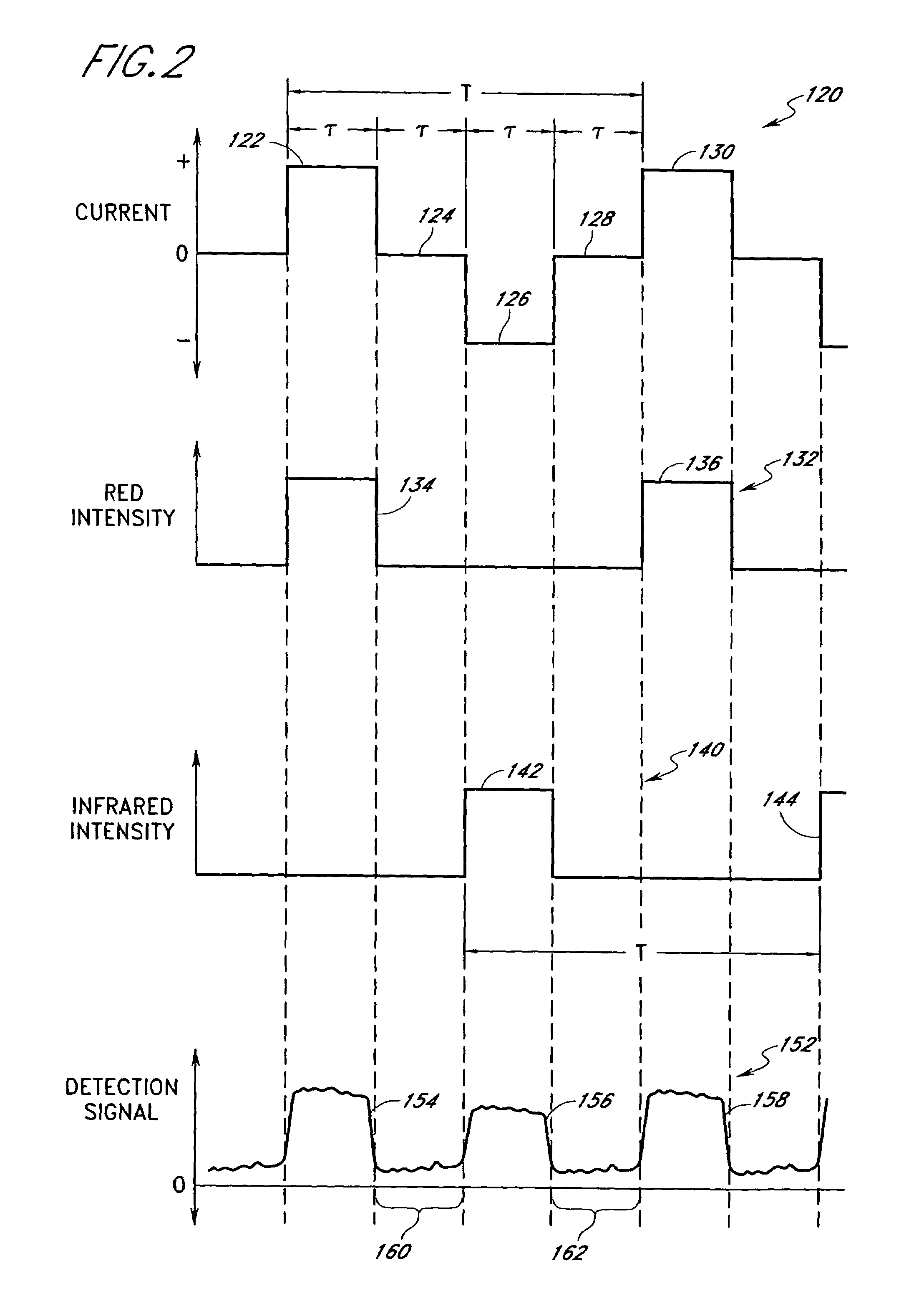
[0010]Another aspect of the present invention is a method of minimizing crosstalk between two signals generated by applying a first pulse and a second pulse to measure a parameter. The first pulse and the second pulse are applied periodically at a first repetition rate defining a period. The first pulse is generated during a first interval in each period, and the second pulse is generated during a second interval in each period. The second interval is spaced apart from the first interval. The first and second pulses produce first and second parametric signals responsive to the parameter. The first and second parametric signals are received by a single detector that outputs a composite signal responsive to the first and second parametric signals. The method comprises the step of applying a first demodulation signal to the composite signal to generate a first demodulated output signal wherein the first demodulation signal comprises at least a first component having a first frequency corresponding to the first repetition rate. The first component has a first amplitude. The first demodulation signal further comprises a second component having a second frequency that is a harmonic of the first frequency. The second component has a second amplitude which has a selected proportional relationship to the first amplitude. The method further includes the step of applying a second demodulation signal to the composite signal to generate a second demodulated output signal. The second demodulation signal comprises the first component at the first frequency and the first amplitude and further comprises the second component at the second frequency and the second amplitude. At least one of the first and second components of the second demodulation signal has a selected phase difference with respect to the corresponding one of the first and second components of the first demodulation signal. The method further includes the steps of lowpass filtering the first demodulated output signal to generate a first recovered output signal responsive to the first parametric signal; and lowpass filtering the second demodulated output signal to generate a second recovered output signal responsive to the second parametric signal.
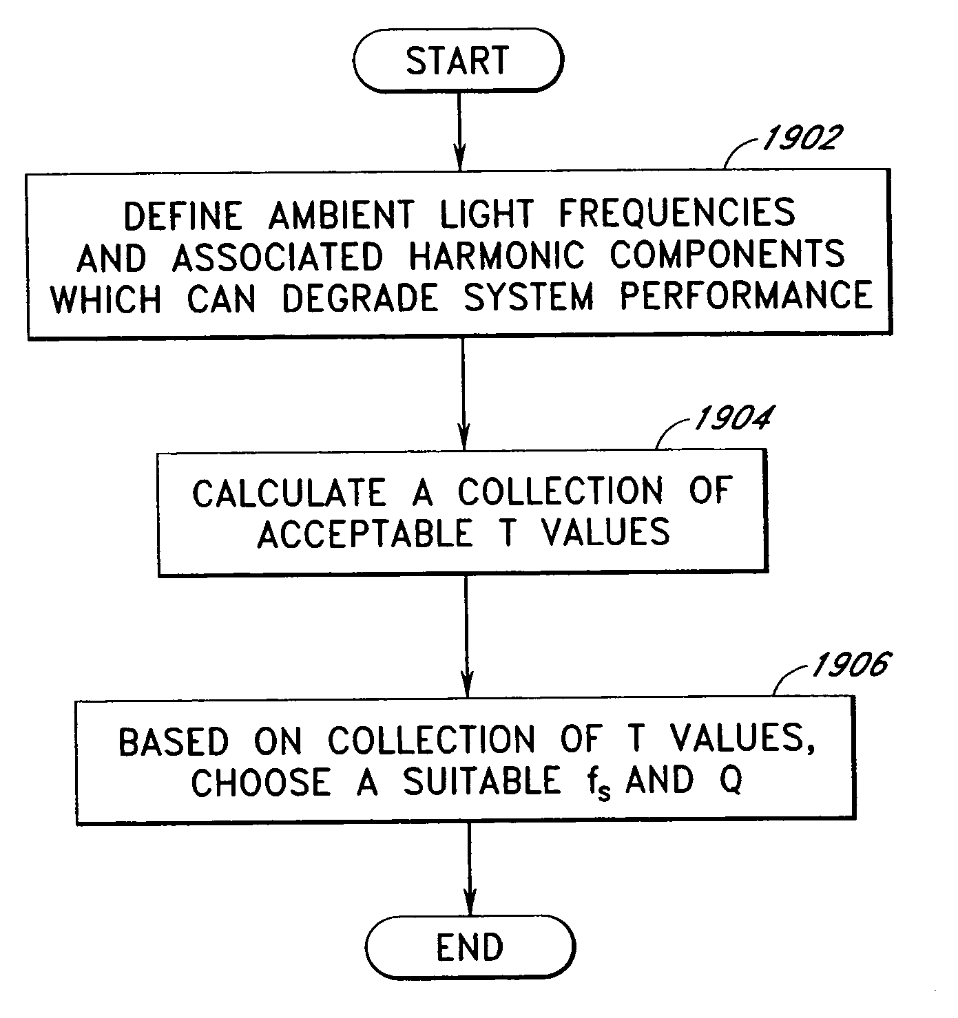
[0019]Another embodiment of the invention is a method for selecting a sample rate that reduces the interference caused by ambient light.

Problems solved by technology

In conventional time division multiplexing (TDM) demodulation that uses rectangular waves to drive the red and infrared LEDs, the conventional process of demodulation using square waves can result in the aliasing of the ambient noise components that come close to the sidebands of harmonics and the fundamental frequency of the rectangular waves, and the noise components are thus collapsed into the output signal generated by the demodulation.
In particular, it is very difficult to avoid including harmonics of the line frequency in the demodulated output signal.

Method used


Image

  • Method and apparatus for demodulating signals in a pulse oximetry system
  • Method and apparatus for demodulating signals in a pulse oximetry system
  • Method and apparatus for demodulating signals in a pulse oximetry system

Examples


Embodiment Construction

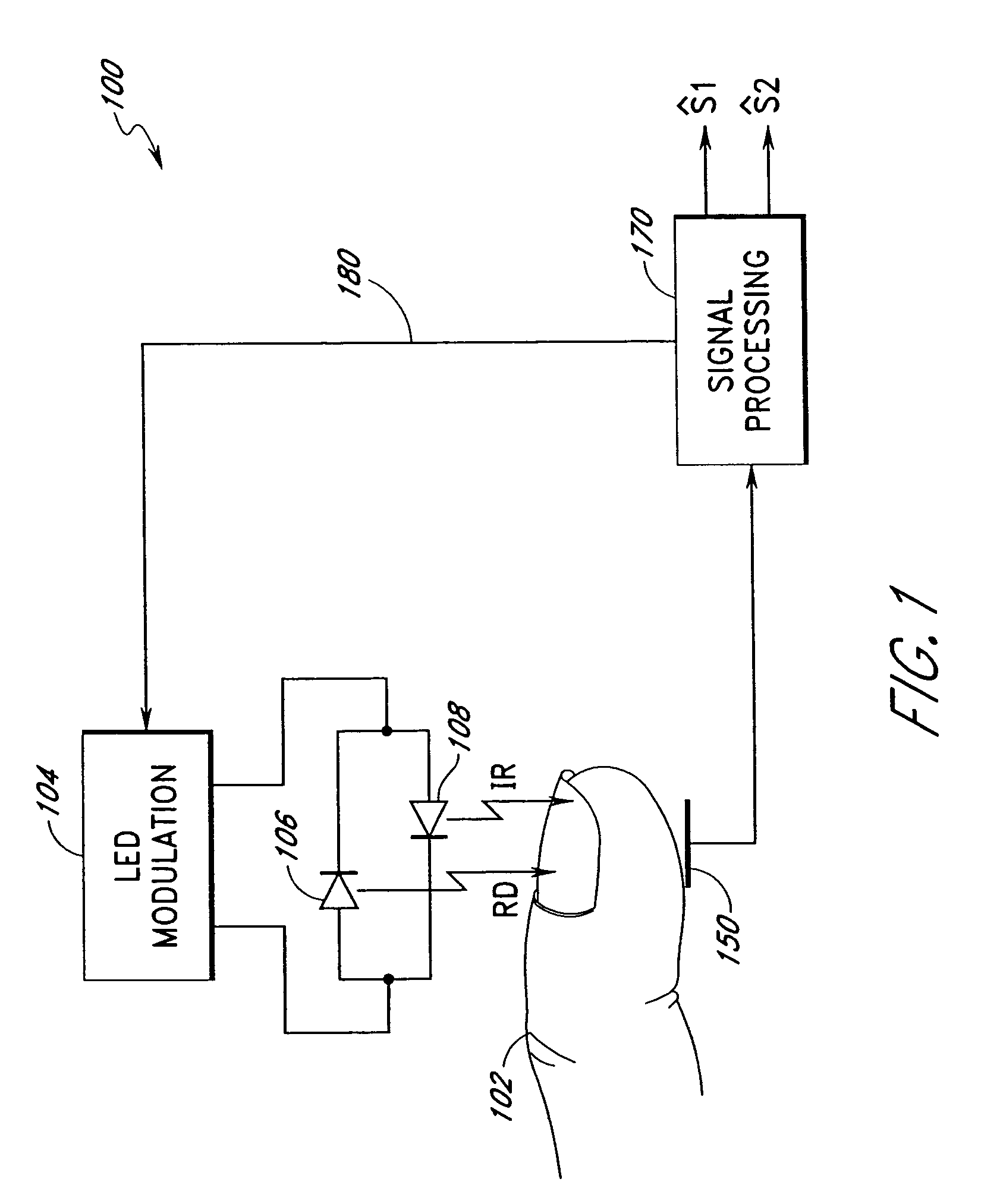
[0041]FIG. 1 illustrates an exemplary block diagram of a representation of a signal processing system 100 in accordance with the present invention used to determine blood oxygen saturation in a subject, such as, for example, a human subject. In the example presented, the measurements are performed on a portion of the subject, such as a finger 102 illustrated in FIG. 1. An LED modulation circuit 104 drives a pair of back-to-back light emitting diodes (LEDs) 106, 108 by applying a periodic signal to the two light emitting diodes 106, 108. The LED 106 is selected to emit electromagnetic energy in the red visible light range, and has a wavelength of, for example, approximately 660 nanometers. The LED 108 is selected to emit electromagnetic energy in the infrared range, and has a wavelength of, for example, approximately 905 nanometers. The LED modulation circuit 104 supplies current in alternating directions so that the two LEDs 106, 108 are activated one at a time. In particular, as il...


PUM


Abstract

A method and an apparatus measure blood oxygenation in a subject. A first signal source applies a first input signal during a first time interval. A second signal source applies a second input signal during a second time interval. A detector detects a first parametric signal responsive to the first input signal passing through a portion of the subject having blood therein. The detector also detects a second parametric signal responsive to the second input signal passing through the portion of the subject. The detector generates a detector output signal responsive to the first and second parametric signals. A signal processor receives the detector output signal and demodulates the detector output signal by applying a first demodulation signal to a signal responsive to the detector output signal to generate a first output signal responsive to the first parametric signal. The signal processor applies a second demodulation signal to the signal responsive to the detector output signal to generate a second output signal responsive to the second parametric signal. The first demodulation signal and the second demodulation signal both include at least a first component having a first frequency and a first amplitude and a second component having a second frequency and a second amplitude. The second frequency is a harmonic of the first frequency. The second amplitude is related to the first amplitude to minimize crosstalk from the first parametric signal to the second output signal and to minimize crosstalk from the second parametric signal to the first output signal.

Description

REFERENCE TO PRIOR RELATED APPLICATION[0001]This application is a divisional of U.S. application Ser. No. 09 / 735,960 (now U.S. Pat. No. 6,643,530) filed Dec. 13, 2000, which is a divisional of U.S. application Ser. No. 09 / 058,799 (now U.S. Pat. No. 6,229,056) filed Apr. 10, 1998, which is a continuation-in-part of U.S. application Ser. No. 09 / 005,898 (now U.S. Pat. No. 5,919,134) filed Jan. 12, 1998 which claims priority from U.S. Provisional Application No. 60 / 043,620 filed Apr. 14, 1997.BACKGROUND OF THE INVENTION[0002]1. Field of the Invention[0003]The present invention relates to the field of signal processing, and, more particularly, relates to the field of processing of signals generated in a physiological monitoring system, such as, for example, in a system for measuring blood oxygen saturation using pulse oximetry.[0004]2. Description of the Related Art[0005]The present invention will be described herein in connection with a pulse oximetry apparatus and a method, which are u...

Claims


Application Information

Patent Timeline
IPC IPC(8): A61B5/00A61B5/1455A61B5/145
CPCA61B5/14551A61B5/7228H04J14/08H04J3/10A61B5/7217A61B2560/0242A61B5/7232A61B5/14552A61B5/1495A61B5/7203A61B2562/0238
Inventor DIAB, MOHAMED K.WEBER, WALTER M.AL-ALI, AMMAR
Owner JPMORGAN CHASE BANK NA
Learn More