
Pulse oximetry sensor adaptor

Inactive Publication Date: 2006-01-31
JPMORGAN CHASE BANK NA
View PDF19 Cites 1146 Cited by
  • Summary
  • Abstract
  • Description
  • Claims
  • Application Information

AI Technical Summary

Benefits of technology

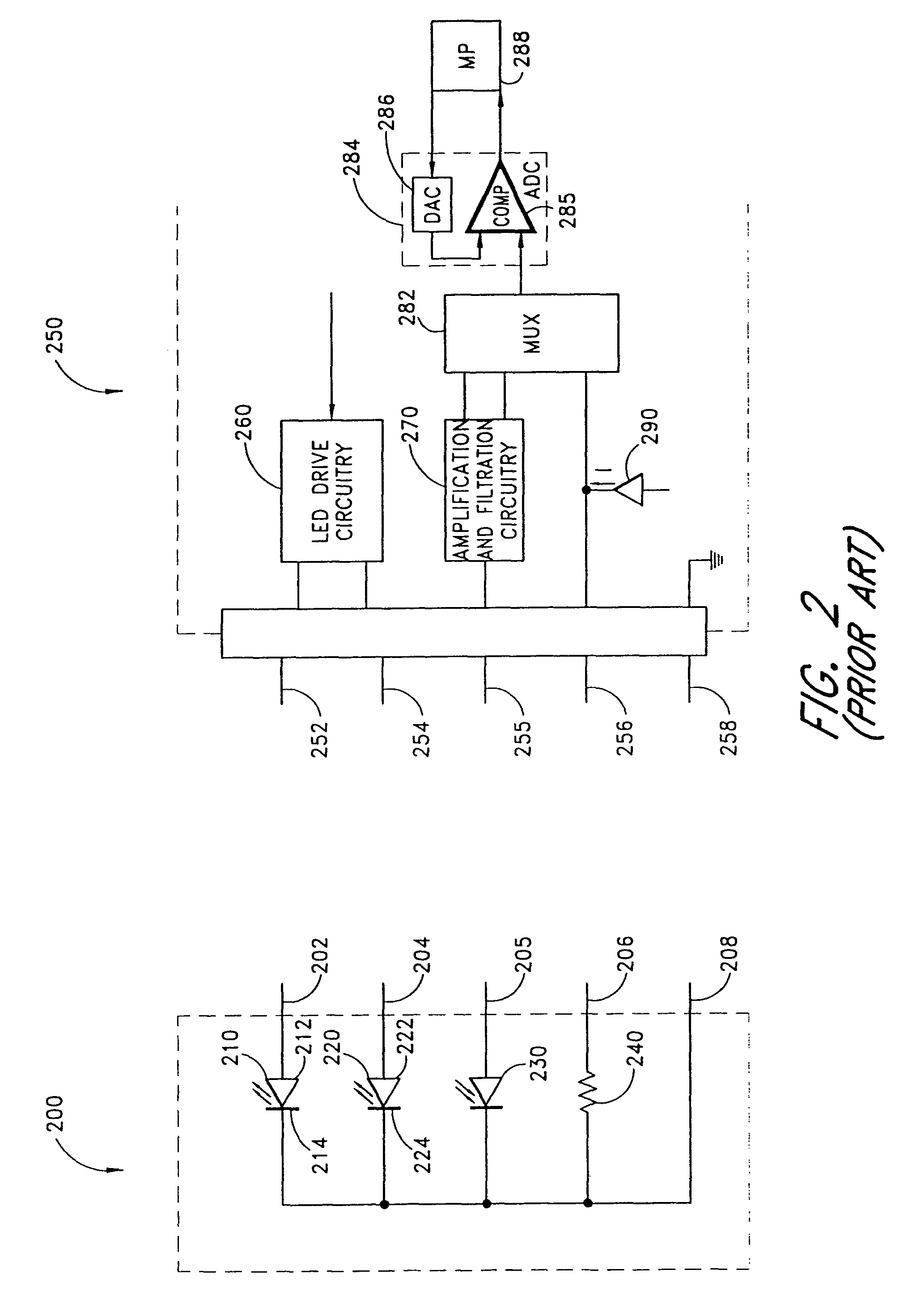
[0017]The detector portion of the sensor 300 of FIG. 3 also differs from those in the previously miniature described sensors in that a gain resistor 340 is connected to the photodiode 330. When connected to the corresponding monitor 350, the gain resistor 340 provides feedback, which adjusts the gain of a monitor preamplifier within the signal conditioner portion 380 of the monitor 350, which reduces the preamplifier dynamic range requirements. For example, if the sensor 300 is configured for neo-natal patients, where the sensor site is of relatively narrow thickness and the skin relatively transparent, the gain can be correspondingly low. However, if the sensor 300 is configured for adult patients, with a relatively thick and opaque sensor site, such as a finger, the gain can be correspondingly higher to compensate for lower detected intensities.
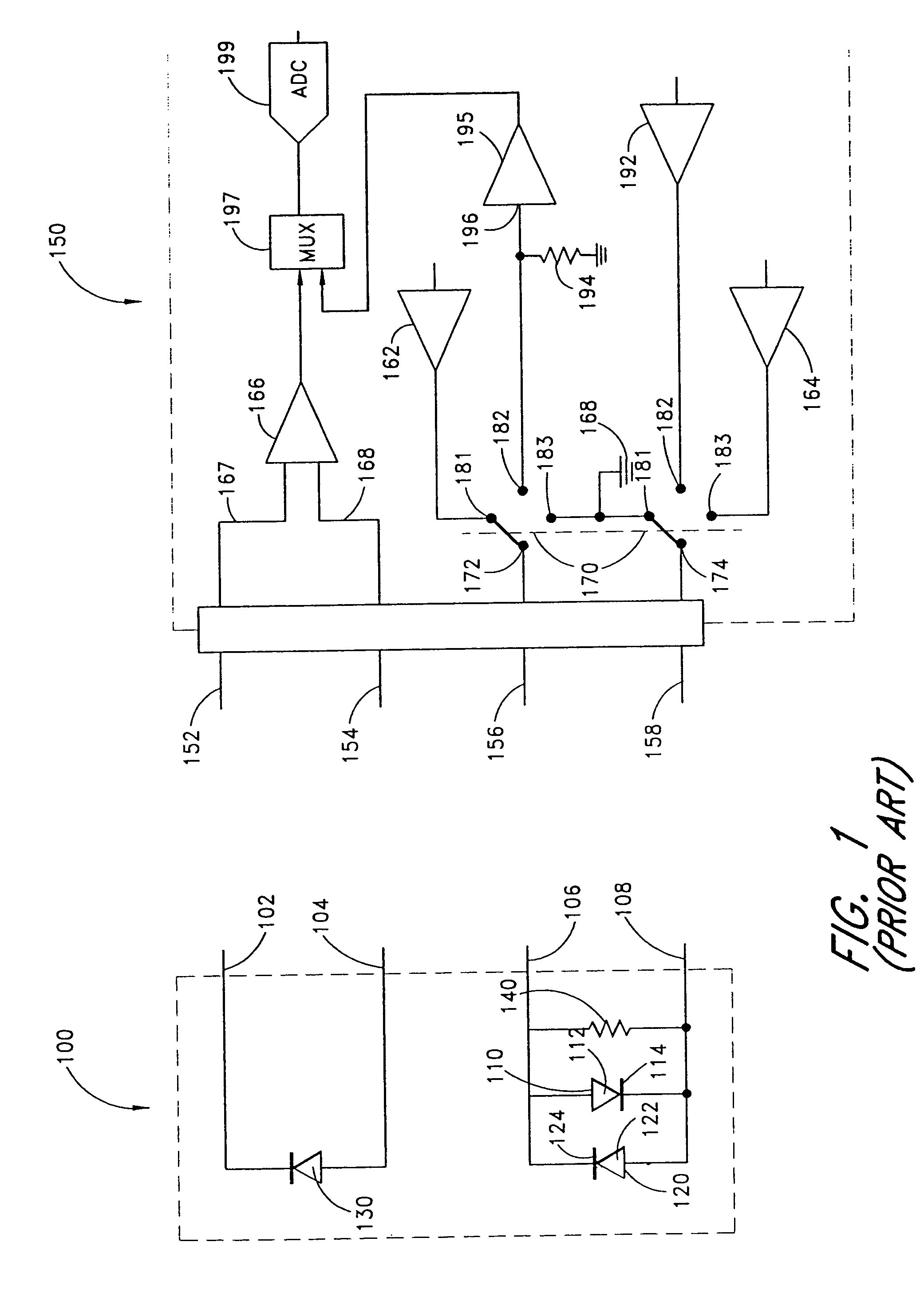
[0021]Although it is perhaps possible to design sensors that accommodate a variety of monitors, such sensors would be, for the most part, commercially impractical. For one, pulse oximetry sensors can be either reusable or disposable. In the case of disposable sensors, cost per sensor is critical. Even for reusable sensors, cost and complexity are important design factors. A universal sensor having integrated adapter components could be significantly more expensive than the sensors described in FIGS. 1 through 3. A sensor adapter according to the present invention solves many of the problems associated with both sensor and monitor compatibility and the need to avoid sensor complexity.

Problems solved by technology

A drawback to conventional pulse oximetry systems is the lack of standardization of the sensor and the monitor.
This incompatibility is mainly due to physical configuration and signal parameter differences among both the sensors and the monitors.

Method used


Image

  • Pulse oximetry sensor adaptor
  • Pulse oximetry sensor adaptor
  • Pulse oximetry sensor adaptor

Examples


Embodiment Construction

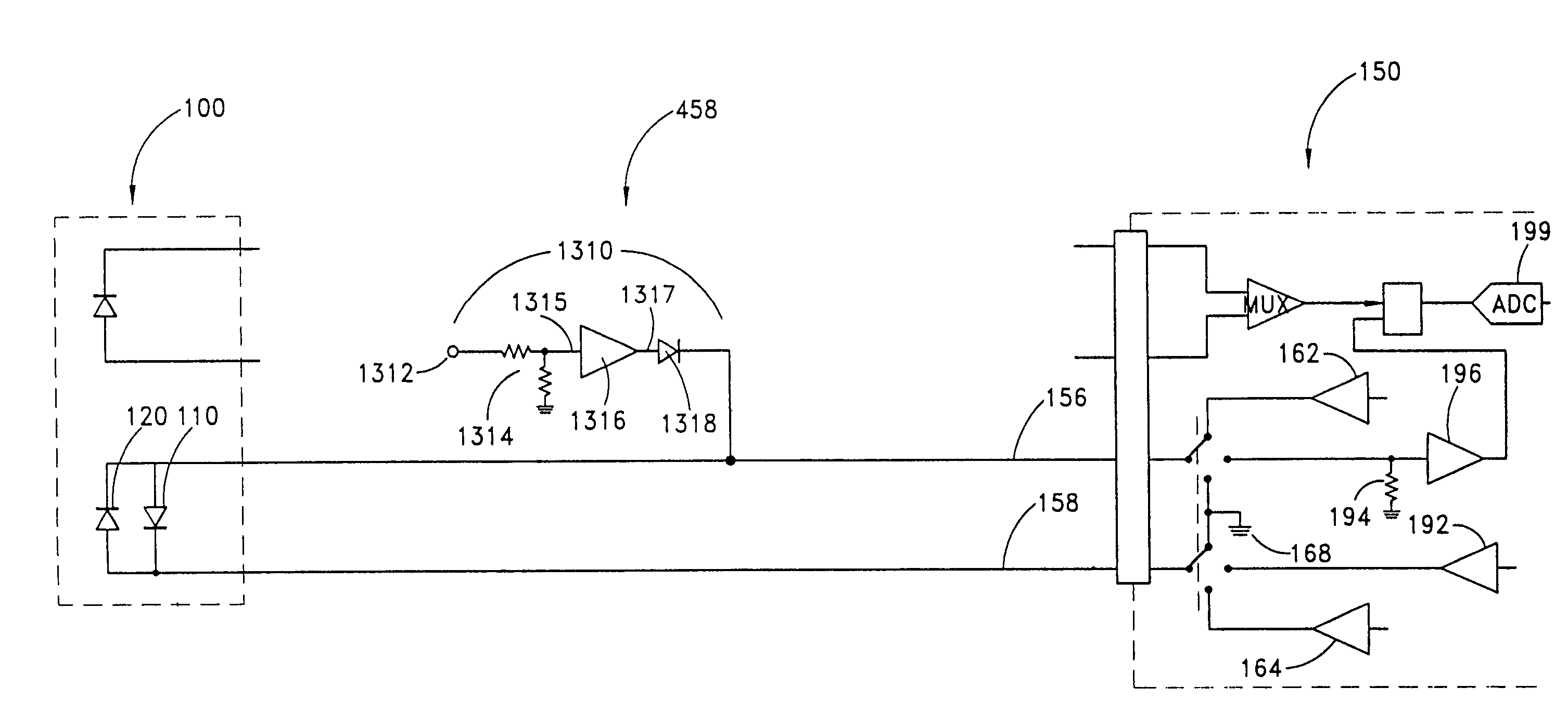
[0045]FIG. 4 shows a functional block diagram of a sensor adapter 400 for interconnecting a sensor 402 to an incompatible monitor 404 in a pulse oximetry system. Interconnecting the monitor light source driver 410 with the sensor light source 412 are a light source configuration 414 adapter and a drive limit 418 adapter. The light source configuration 414 element adapts the light source driver 410 to the particular configuration of the sensor light source 412, such as two-wire, back-to-back LEDs, three-wire, common-anode LEDs and three-wire, common-cathode LEDs. The drive limit 418 element increases or decreases the current of the light source driver 410 to adapt to the requirements of the sensor light source 412.

[0046]Also shown in FIG. 4 is an active gain 434 element, which adapts the sensor light detector 432 to the monitor signal conditioner 430. Active gain 434 sets the amount of amplification of the signal from the sensor light detector 432 that occurs in the monitor signal co...


PUM


Abstract

An adapter allows the interconnection of a sensor originating from one manufacturer to be coupled with conventionally incompatible monitors originating from other manufacturers to form a properly functioning pulse oximetry system. The adapter matches a sensor driver in a monitor to the current requirements and light source configuration of a sensor. The adapter also matches a sensor's light detector signal level to the dynamic range requirements of a monitor preamplifier. Further, the adapter provides compatible sensor calibration, sensor type and security information to a monitor. The adapter may have a self-contained power source or it may derive power from the monitor, allowing both passive and active adapter components. The adapter is particular suited as an adapter cable, replacing a conventional patient cable or sensor cable as the interconnection between a sensor to a monitor in a pulse oximetry system.

Description

RELATED APPLICATION[0001]This is a continuation application based on application Ser. No. 09 / 982,453, filed Oct. 17, 2001, now U.S. Pat. No. 6,597,933, which is a divisional of application Ser. No. 09 / 404,060, filed Sep. 23, 1999, now U.S. Pat. No. 6,349,228, which is a continuation of application Ser. No. 09 / 021,957, filed on Feb. 11, 1998, now U.S. Pat. No. 5,995,855, the entirety of which is incorporated herein by reference.BACKGROUND OF THE INVENTION[0002]Oximetry is the measurement of the oxygen status of blood. Early detection of low blood oxygen is critical in the medical field, for example in critical care and surgical applications, because an insufficient supply of oxygen can result in brain damage and death in a matter of minutes. Pulse oximetry is a widely accepted noninvasive procedure for measuring the oxygen saturation level of arterial blood, an indicator of oxygen supply. A pulse oximetry system consists of a sensor attached to a patient, a monitor, and a cable conne...

Claims


Application Information

Patent Timeline
IPC IPC(8): A61B5/00
CPCA61B5/14551A61B5/14552Y10S439/909A61B2562/222
Inventor KIANI, MASSI E.SMITH, ROBERT A.TOBLER, DAVID R.
Owner JPMORGAN CHASE BANK NA
Learn More