Light Emission Device and Light Emitter Using the Same

a technology of light emission device and light emission device, which is applied in the direction of semiconductor devices for light sources, lighting and heating apparatus, transportation and packaging, etc., can solve the problems of high power consumption, insufficient luminance may not be achieved for required purposes, and uneven light application from lighting equipment on the whole to objects, etc., to achieve high luminance, reduce power consumption, and easily alter the shape and size of transparent elements

Inactive Publication Date: 2009-07-02
LITEHOUSE TECH CORP
View PDF13 Cites 40 Cited by
  • Summary
  • Abstract
  • Description
  • Claims
  • Application Information

AI Technical Summary

Benefits of technology

[0011]In accordance with the present invention, the transparent element has the curved surface region of substantially arcuate or circular shape in section and also has a property that allows substantive light to pass therethrough, and a light is applied from the light source to such curved surface region of transparent element. In this respect, the present invention utilizes a lens effect to the light, which is caused by that curved surface region. Accordingly, a whole of the transparent element can be illuminated uniformly with a high luminance to provide a satisfied bright illumination that fulfills desired purposes, and also, it is possible to easily alter the shape and size of the transparent element, according to requirements. Further, in the present invention, an LED(s) is / are employed as the light source, which makes it possible to reduce power consumption, and a heat radiation may be provided, as required, to suppress increase of temperature.

Problems solved by technology

However, in general, many of lighting equipments using LEDs are faced with the problem that the light quantity thereof is low and insufficient relative to that of the incandescent lamp or the like, and therefore, a sufficient luminance may not be attained for required purpose, depending on a circumstance where the lighting equipment is installed or used.
In particular, in the case of a linear (rectilinear) form of lighting equipment using one single LED, it is generally conceived that the lighting region thereof becomes higher in luminance as it proceeds closer to a light source, while becoming lower in luminance as it proceeds away from the light source, and therefore, it is of a high likelihood that an uneven luminance of light may be applied from the lighting equipment on the whole to an object which will thus be illuminated unevenly therewith.
Consequently, if it is desired to create a uniform band of light of a more satisfied luminance with such prior art, additional many numbers of LEDs are required to be arranged in the foregoing manner, which nonetheless results in being a bar to reduction of power consumption and in undesired increase in size of the lighting equipment as well as in costs for assembly of that lighting equipment.
What is worse, if such many arrays of LEDs remain in “on” state for continued emission of the band of light, a temperature surrounding them is inevitably increased to a certain high degree, although such increased degree of temperature is lower than an increased degree of temperature caused by many fluorescent lamps or incandescent lamps used in the same situation.

Method used


Image

  • Light Emission Device and Light Emitter Using the Same
  • Light Emission Device and Light Emitter Using the Same
  • Light Emission Device and Light Emitter Using the Same

Examples


embodiment 1

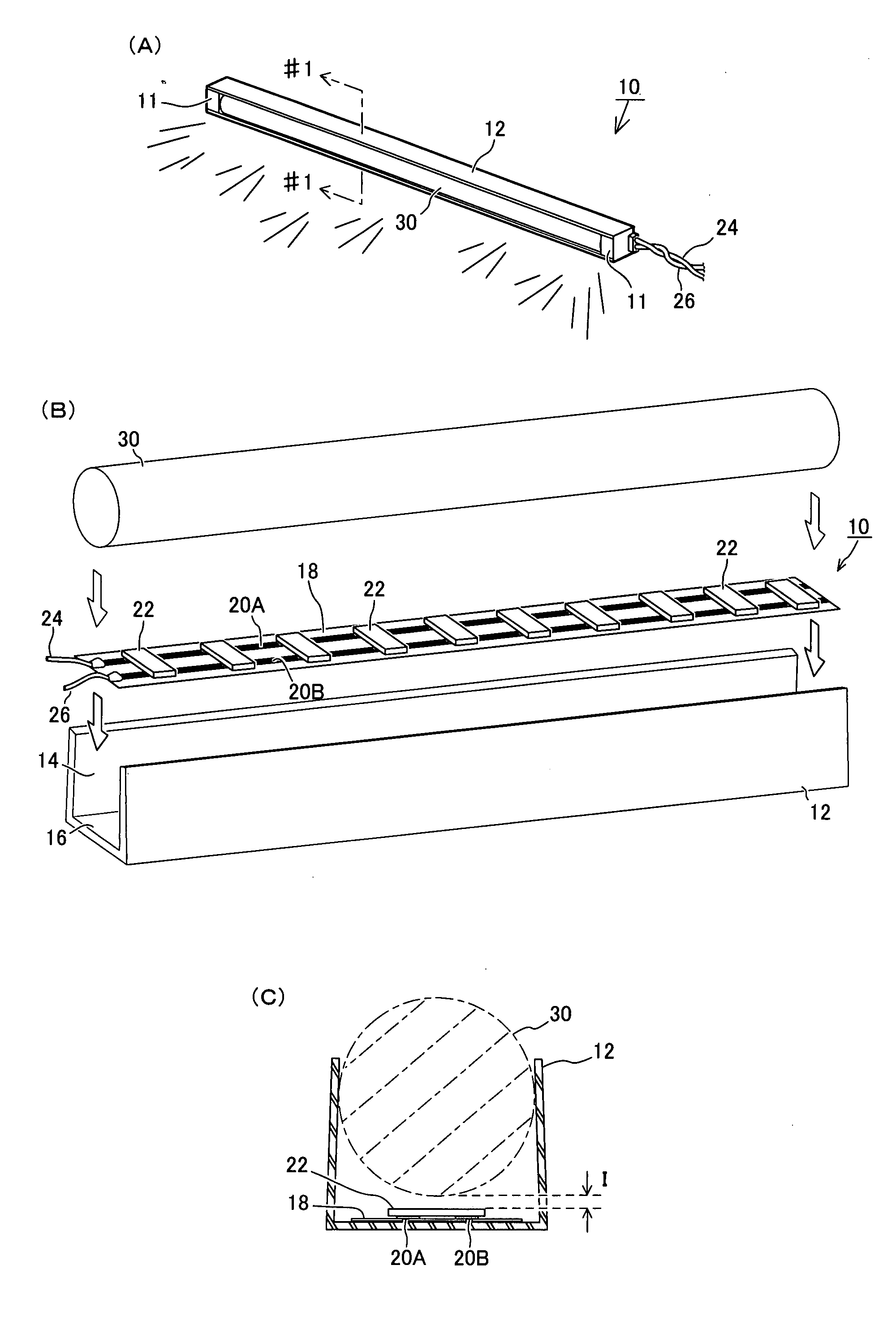
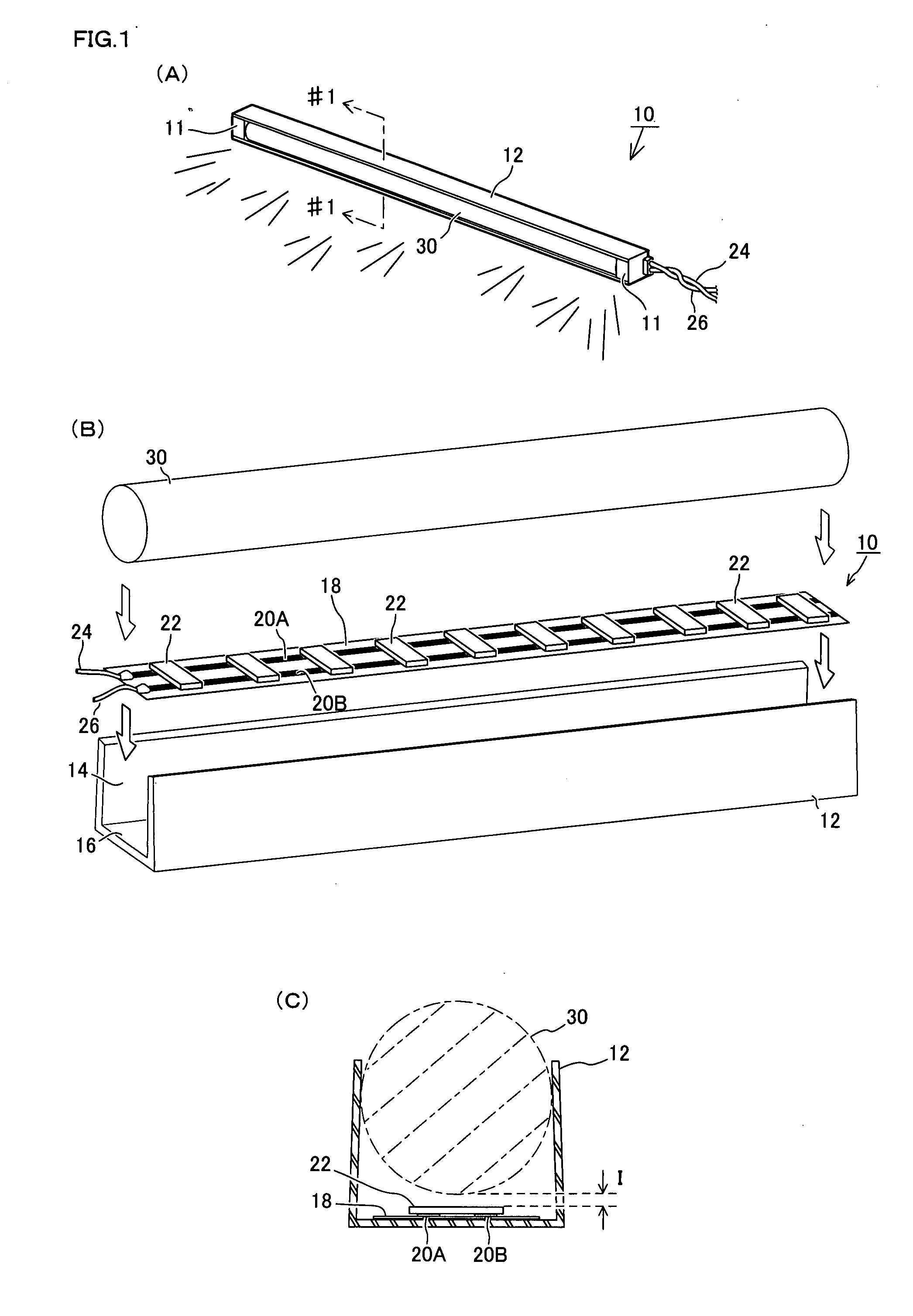
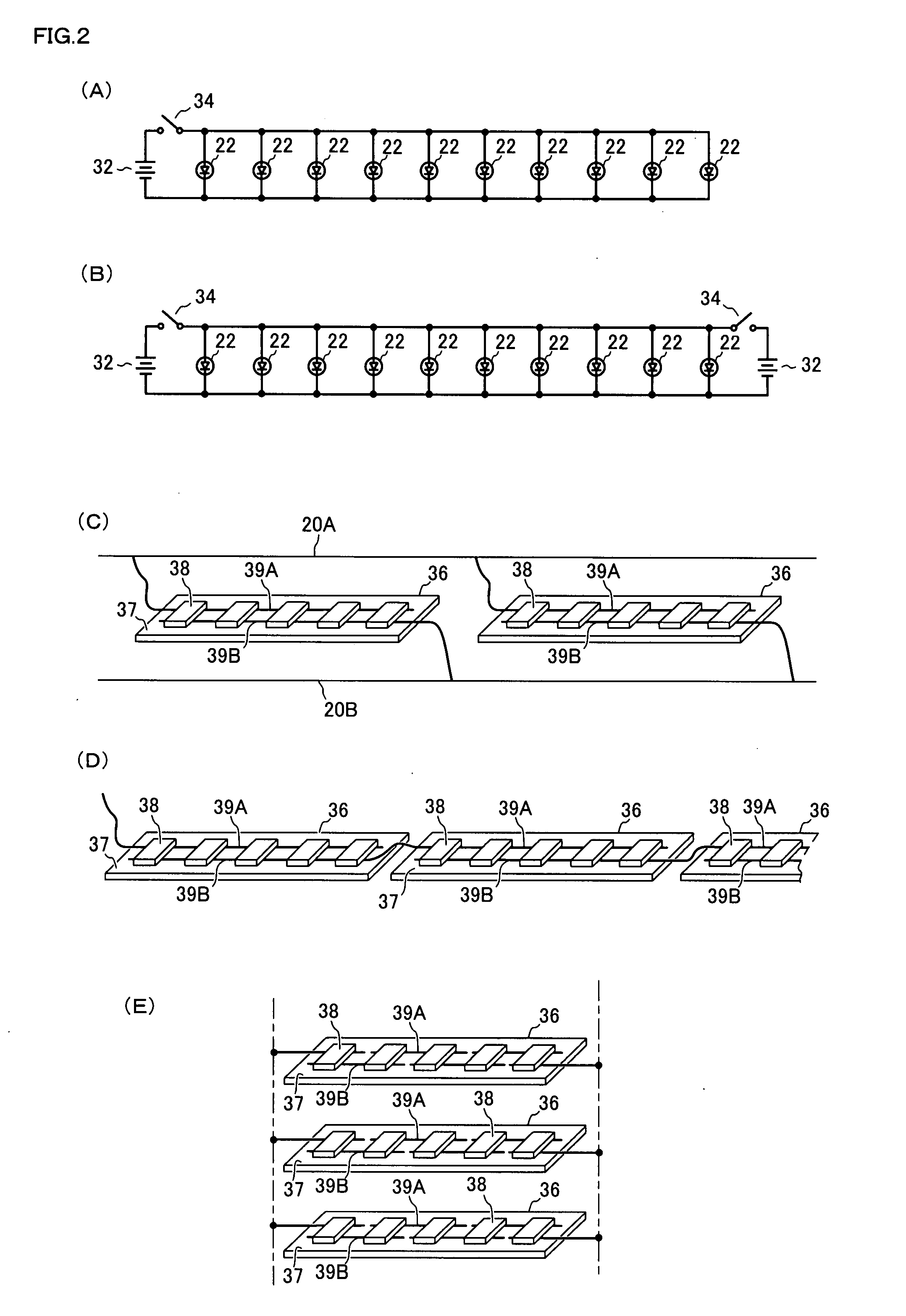
[0170]First of all, referring to FIGS. 1 and 2, a specific description will be made of a 1st embodiment of the present invention. FIG. 1(A) is a perspective view showing an outer appearance of the present embodiment of light emission device. FIG. 1(B) is an exploded schematic perspective view of the same. FIG. 1(C) is a sectional view taken along the line #1-#1 of FIG. 1(A), which shows a corresponding section of this embodiment as viewed in the arrow direction of the FIG. 1(A). FIG. 2 provides circuit diagrams in the present mode of light emission device. The present embodiment is an example applied to a linearly extending mode of lighting equipment which is adaptable for various uses and purposes. Namely, in this particular embodiment, a light emission device 10 is provided, according to which, there are provided LEDs 22, a light source, and a transparent element 30 of a columnar shape having a substantially circular shape in section, which is disposed adjacent to the LEDs 22, and...

embodiment 2

[0180]Reference being made to FIG. 3, a specific description will now be made of a 2nd embodiment of the present invention. FIG. 3(A) is a sectional view showing a principal part of the present embodiment. FIG. 3(B) is a sectional view showing a principal part of modified mode of the present embodiment. FIG. 3(C) is a perspective view showing another modified mode of the present embodiment. As similar to the previously described Embodiment 1, the present embodiment also employs a long columnar transparent element, but its purpose is to effectively suppress an increase of temperature or to keep the temperature to a low degree, by positively causing radiation of heat. At first, referring to FIG. 3(A), a light emission device 40 is provided, which comprises: a plurality of LEDs 60 as a light source; and a substrate 56 on which the LEDs are mounted, such that those LEDs 60 and substrate 56 are accommodated in a light cover 50 of substantially channel shape in section. The light cover 50...

embodiment 3

[0185]Reference being now made to FIGS. 4 and 5, a description will be made of the 3rd embodiment of the present invention. While the above-described Embodiments 1 and 2 utilize a rectilinear configuration of transparent element, the present third embodiment is directed to a light emission device having a ring configuration of transparent element. FIG. 4(A) is a plan view showing an outer appearance of light emission device of the present embodiment. FIG. 4(B) is a sectional view taken along the line #4-#4 in FIG. 4(A), which shows a corresponding section as viewed in the arrow direction of the FIG. 4(A). FIG. 5 is a perspective view showing the state where a transparent element is removed form the light emission device of the present embodiment.

[0186]A light emission device 70 in this third embodiment is provided as a ring (or annular) shape of lighting equipment that can be installed at a given location, and comprises: a transparent element 78 having a property that allows substan...


PUM


Abstract

The present invention aims at: emitting a uniform light on the whole with a high luminance to provide a required bright illumination; suppressing increase of temperature and reducing power consumption; and permitting easy alteration of entire shape and size thereof.
A light emission device 10 is provided, which comprises: a transparent element 30 of columnar shape having a substantially circular shape in section; a light cover 12 attached on outer surface of the transparent element 30 so as to securely sandwich and retain that particular outer surface of transparent element; and a plurality of LEDs 22 for applying lights to the transparent element 30, the plurality of LEDs 22 being provided in the light cover 12. Such LEDs 22 are disposed relative to said transparent element 30, such that a predetermined space I is essentially given between the LEDs 22 and the surface of the transparent element 30. Upon lights being emitted from the LEDs 22, the lights expands freely in an air zone between the LEDs 22 and the transparent element 30 and are therefore applied to that particular transparent element 30 from many angles. Then, the lights are refracted and diffused due to a lens effect of the transparent element 30, and emitted from an opening area 14 of the light cover 12 to the outside. When such light emission is viewed from the outside, it is observed that a whole of the transparent element 30 is illuminated uniformly with a high luminance.

Description

TECHNICAL FIELD[0001]The present invention relates to a light emission device and a light emitter using the light emission device. More particularly, the invention is directed to an improvement of a light emission device which comprises a transparent element and a means for introducing a light into and through the transparent element, as well as to an improvement of light emitter using that light emission device, in order to materialize a high luminance and uniformity of a light emitted therefrom.BACKGROUND ART[0002]Lighting equipment or luminaire, such as a fluorescent lamp, used in individual homes, offices, hospitals and other facilities, has a reflector member disposed behind or laterally of a light source. With such arrangement, a light emitted from the light source (e.g. fluorescent lamp or incandescent lamp) is directed to the reflector member and reflected thereby in a desired direction to a side or object to be illuminated. Due to such light reflection effect, a luminance o...

Claims


Application Information

Patent Timeline
Patent Type & Authority Applications(United States)
IPC IPC(8): F21V1/00
CPCF21K9/00F21S4/008F21S48/215F21S48/218F21V5/043F21V7/0025F21Y2101/02H01L2924/0002F21Y2103/003H01L25/0753H01L33/58H01L2924/00F21S4/28F21Y2103/10F21Y2115/10F21K9/68F21S43/14F21S43/15
Inventor DAIMON, SUEYOSHI
Owner LITEHOUSE TECH CORP
Why Eureka
Try Eureka