Image forming apparatus, and method of controlling warming-up time of image forming apparatus

a technology of image forming apparatus and fixing unit, which is applied in the direction of electrographic process apparatus, instruments, optics, etc., can solve the problems of time mode drawbacks, user inconvenience and frustration, and failure to fix

Active Publication Date: 2009-07-02
RICOH KK
View PDF2 Cites 116 Cited by
  • Summary
  • Abstract
  • Description
  • Claims
  • Application Information

AI Technical Summary

Problems solved by technology

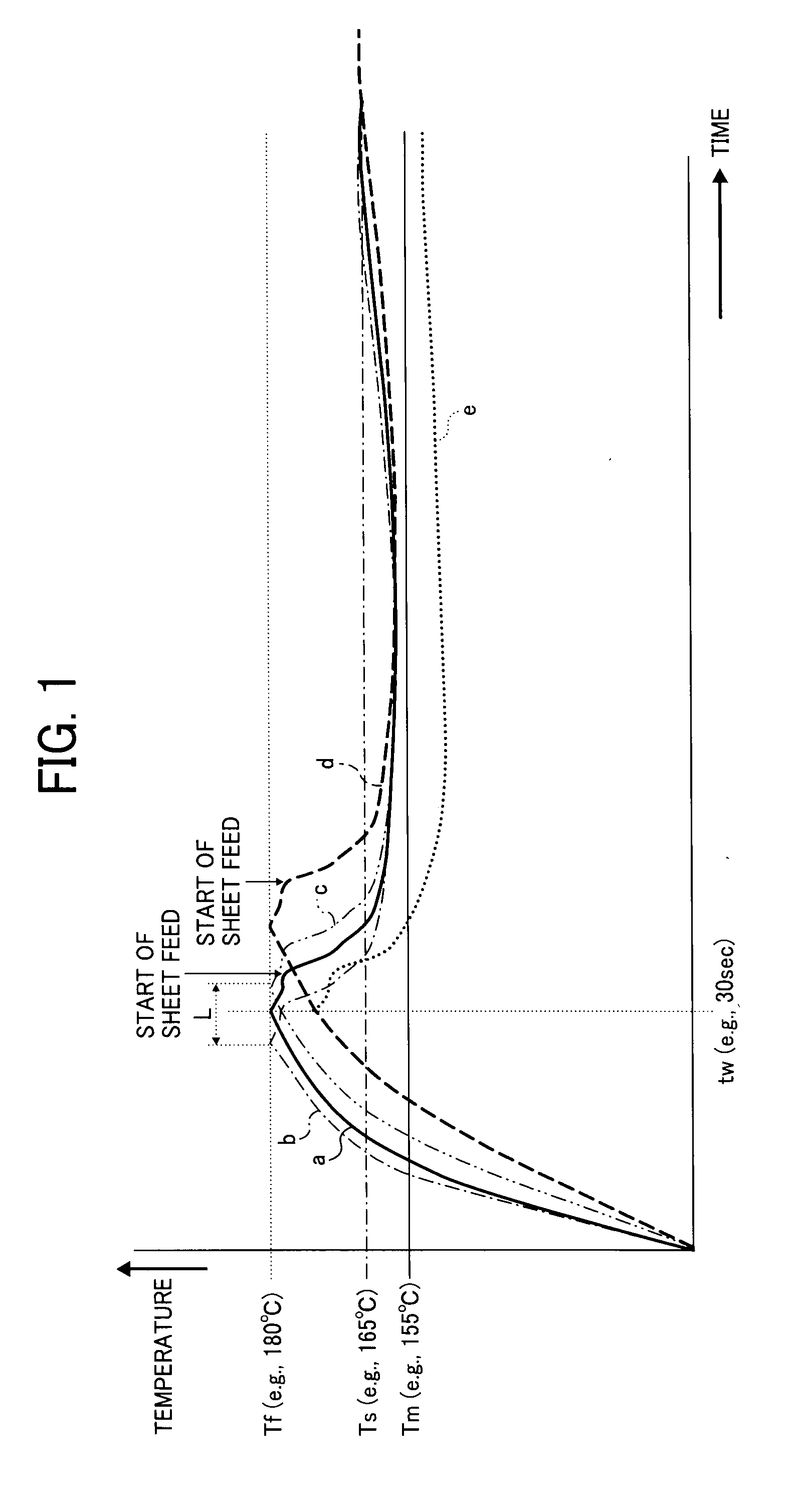
However, a user may feel inconvenience and frustration with such a configuration using the temperature mode because the warming-up time may fluctuate in a given time range.
However, the time mode may have some drawbacks in some cases.
Then the temperature of the fixing member becomes lower than a minimum fixing temperature Tm (e.g., 155 degrees Celcius), and thereby a fixing failure may occur.
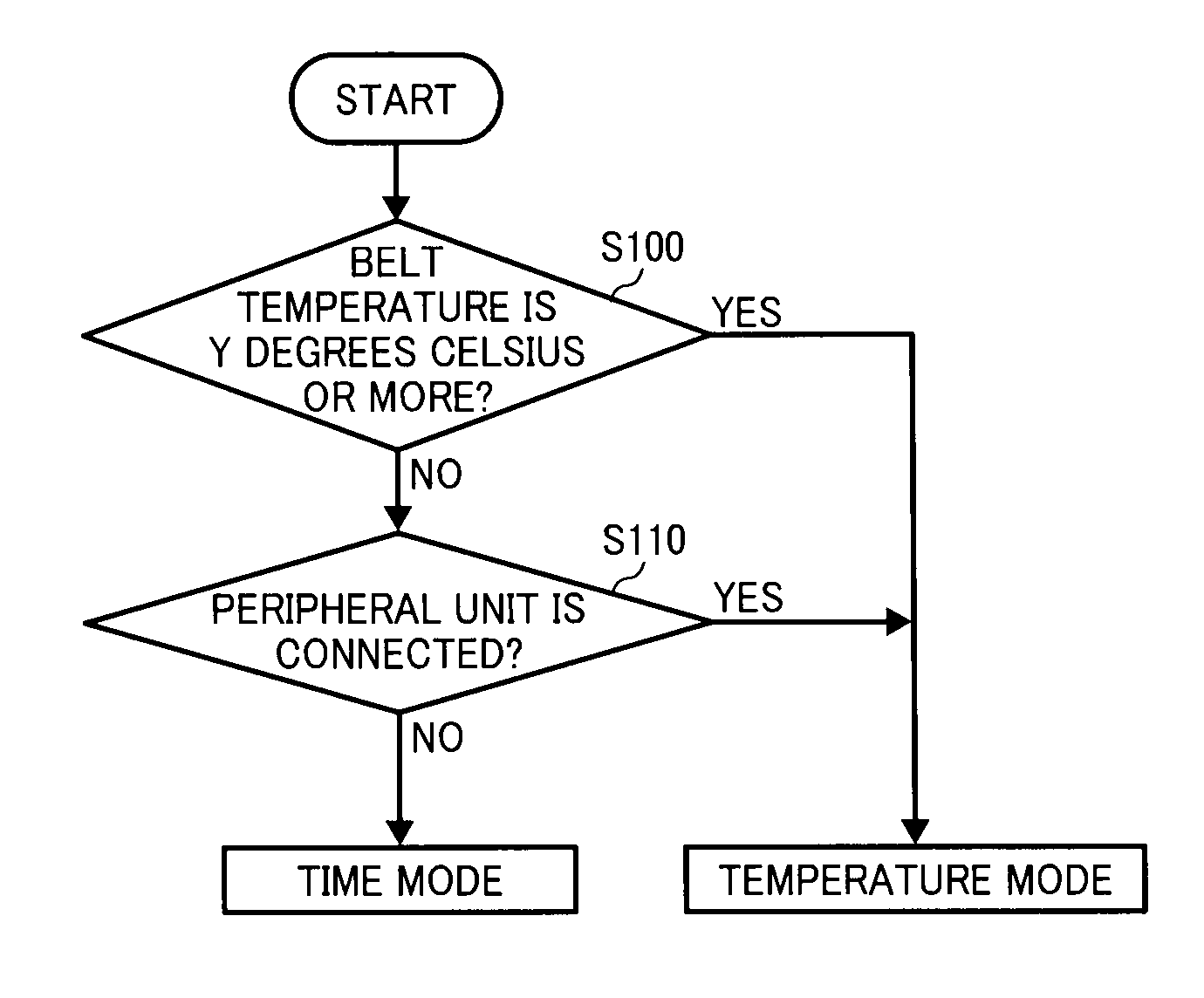
There are several instances in which the heat source of the image forming apparatus might not get enough power to warm up the fixing member to the designated fixing temperature, such as when peripheral units are connected to the image forming apparatus or when the image forming apparatus needs to undergo an image adjustment operation.
Accordingly, electrical power sufficient for the fixing process may not be supplied to the heat source from the single power source because the same single power source needs to supply electrical power used for initialization of the peripheral unit, by which the heat source may not generate sufficient heat energy for heating the fixing member.
Accordingly, if the time mode is employed for the image forming apparatus that is connected to the peripheral unit, the temperature of the fixing member may not be increased to the desired fixing temperature using the time mode, by which a fixing failure may occur.
Accordingly, electrical power sufficient for the fixing process may not be supplied to the heat source from the single power source because the same single power source need to supply electrical power used for the image adjustment operation, by which the heat source may not generate sufficient heat energy for heating the fixing member.
Accordingly, if the time mode is employed for the image forming apparatus which needs the image adjustment operation, the temperature of the fixing member may not be increased to the desired fixing temperature, by which a fixing failure may occur.

Method used


Image

  • Image forming apparatus, and method of controlling warming-up time of image forming apparatus
  • Image forming apparatus, and method of controlling warming-up time of image forming apparatus
  • Image forming apparatus, and method of controlling warming-up time of image forming apparatus

Examples


Embodiment Construction

[0039]A description is now given of example embodiments of the present invention. It should be noted that although such terms as first, second, etc. may be used herein to describe various elements, components, regions, layers and / or sections, it should be understood that such elements, components, regions, layers and / or sections are not limited thereby because such terms are relative, that is, used only to distinguish one element, component, region, layer or section from another region, layer or section. Thus, for example, a first element, component, region, layer or section discussed below could be termed a second element, component, region, layer or section without departing from the teachings of the present invention.

In addition, it should be noted that the terminology used herein is for the purpose of describing particular embodiments only and is not intended to be limiting of the present invention. Thus, for example, as used herein, the singular forms “a”, “an” and “the” are in...


PUM


Abstract

An image forming apparatus includes a fixing unit and a fixing process managing system. The fixing process managing system, including a mode switchover unit, controls a time mode and a temperature mode for heating a fixing member. In the time mode, the fixing unit is determined to be ready for a fixing process when a given time elapses after activation of the image forming apparatus. In the temperature mode, the fixing unit is determined to be ready for a fixing process when a temperature of the fixing member attains a given reference temperature after activation of the image forming apparatus. The mode switchover unit selects between the temperature mode and the time mode. The fixing process managing system selects the temperature mode instead of the time mode when a supply amount of electrical power to the fixing unit is determined to be below a required electrical power supply level.

Description

CROSS-REFERENCE TO RELATED APPLICATIONS[0001]This application claims priority under 35 U.S.C. 119(a) to Japanese Patent Application Nos. 2007-333742, filed on Dec. 26, 2007, and 2008-255917, filed on Oct. 1, 2008 in the Japan Patent Office, the entire contents of each of which are hereby incorporated by reference herein.BACKGROUND OF THE INVENTION[0002]1. Field of the Invention[0003]The present disclosure generally relates to a fixing unit of an image forming apparatus, and more particularly to a method of controlling a warming-up time of a fixing unit of the image forming apparatus.[0004]2. Description of the Background Art[0005]Image forming apparatuses using electrophotography may record an image on a recording medium using a procedure like the following: A rotating photoconductor, such as a photoconductor drum or a photoconductor belt, is charged by a charger; an electrostatic latent image is formed on the photoconductor by directing light onto the photoconductor; the electrosta...

Claims


Application Information

Patent Timeline
Patent Type & Authority Applications(United States)
IPC IPC(8): G03G15/20
CPCG03G15/5004G03G15/2039G03G2215/00978
Inventor KUNII, HIROYUKIFIJIMOTO, IPPEIYOSHINAGA, HIROSHIHACHISUKA, TOSHIHARUISHIGAYA, YASUNORINAMEKATA, SHINICHI
Owner RICOH KK
Why Eureka
Try Eureka