Surveying system

a technology of a surveillance system and a camera is applied in the field of surveillance systems, which can solve the problems and achieve the effect of reducing the working efficiency of the measuring operation

Active Publication Date: 2009-07-02
KK TOPCON
View PDF0 Cites 70 Cited by
  • Summary
  • Abstract
  • Description
  • Claims
  • Application Information

AI Technical Summary

Benefits of technology

[0012]The present invention provides a surveying system, comprising a surveying instrument which measures a distance and an angle by projecting a distance measuring light toward a target can measure a three-dimensional position data of the target and has a function to track the target, and a movable side control device provided on the target side. The surveying instrument has a communication means capable to transmit a three-dimensional position data of the target measured by the surveying instrument to the movable side control device and a first control arithmetic unit for controlling the search of the target by the surveying instrument, the movable side control device has a displacement amount detecting means of the target and a second control arithmetic unit for calculating displacement amount of the target based on a target detection signal from the displacement amount detecting means and for calculating target position based on the displacement amount of the target and based on the three-dimensional position data, and in case the surveying instrument cannot track the target, the target position transmitted from the movable side control device is acquired, and the first control arithmetic unit starts searching of the target with the target position as a starting point. The target position thus obtained is the current position of the target or it is a position very close to the current position of the target. As a result, the target can be detected within a minimum searching range, and the tracking operation can be started promptly.
[0013]Also, the present invention provides the surveying system as described above, comprising a surveying instrument which measures a distance and an angle by projecting a distance measuring light toward a target and can measure a three-dimensional position data of the target and has a function to track the target, and a movable side control device provided on the target side. The surveying instrument has a communication means capable to transmit a three-dimensional position data of the target measured by the surveying instrument to the movable side control device and a first control arithmetic unit for controlling the search of the target by the surveying instrument, the movable side control device has a displacement amount detecting means of the target and a second control arithmetic unit for calculating displacement amount of the target based on a target detection signal from the displacement amount detecting means, and in case the surveying instrument cannot track the target, the displacement amount of the target to be transmitted from the movable side control device is acquired, the first control arithmetic unit calculates a target position based on the three-dimensional position data of the target measured lastly and based on a displacement amount of the target and starts searching of the target with the target position as a starting point. The target position thus obtained is the current position of the target or it is a position very close to the current position of the target. As a result, the target can be detected within a minimum searching range, and the tracking operation can be started promptly.
[0014]Further, according to the present invention, the displacement amount detecting means is an acceleration sensor, and the displacement amount detecting means can be provided by using a low-cost detector.

Problems solved by technology

Further, under working conditions where the optical path is frequently intercepted by the obstacle, there is a problem in that a working efficiency of the measuring operation is extremely decreased.

Method used


Image

  • Surveying system
  • Surveying system
  • Surveying system

Examples


Embodiment Construction

[0021]A description will be given below on the best aspect for carrying out the present invention by referring to the attached drawings.

[0022]First, referring to FIG. 1 to FIG. 3, a description will be given on general features of the surveying system, to which the present invention is applied.

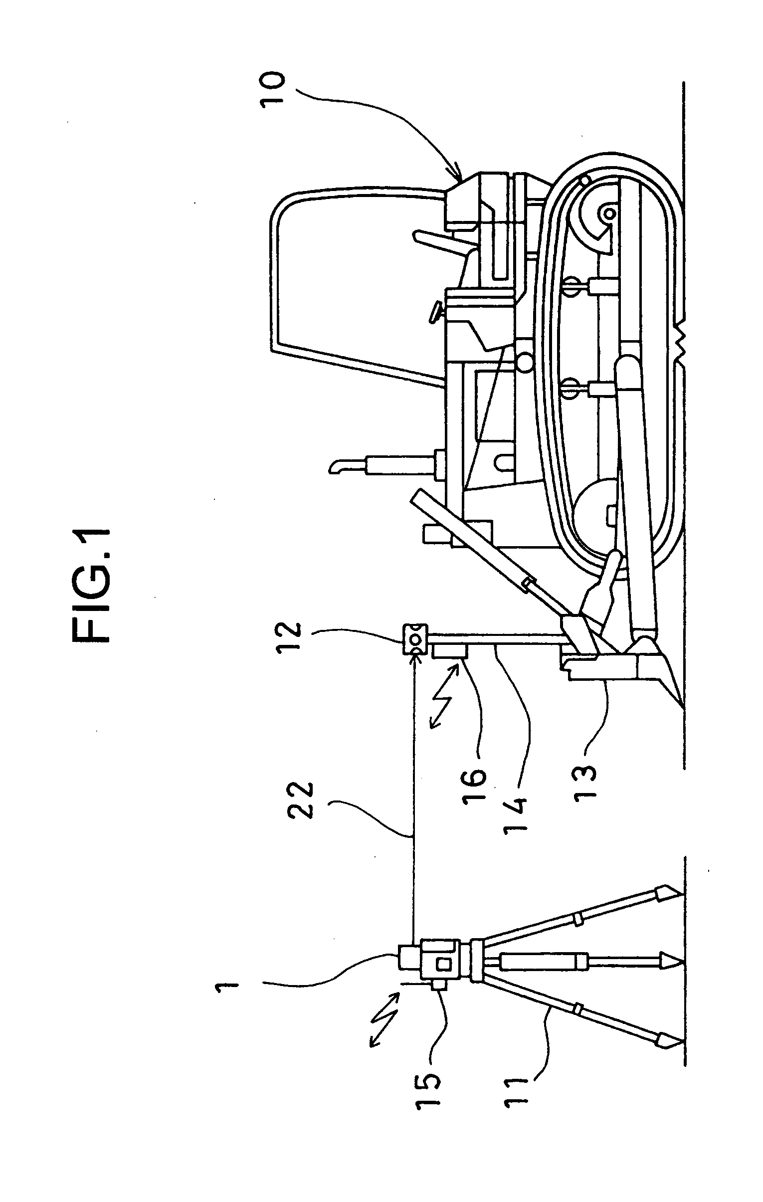
[0023]FIG. 1 shows an example of a surveying system according to the present invention. The figure represents a case where the present invention is applied to civil engineering work using a construction machine 10, e.g. a bulldozer.

[0024]A surveying instrument 1 is installed at a known point via a tripod 11. A target 12 and a movable side control device 16 are installed on a pole 14, which is erected on a bulldozer blade (soil-pushing blade) 13.

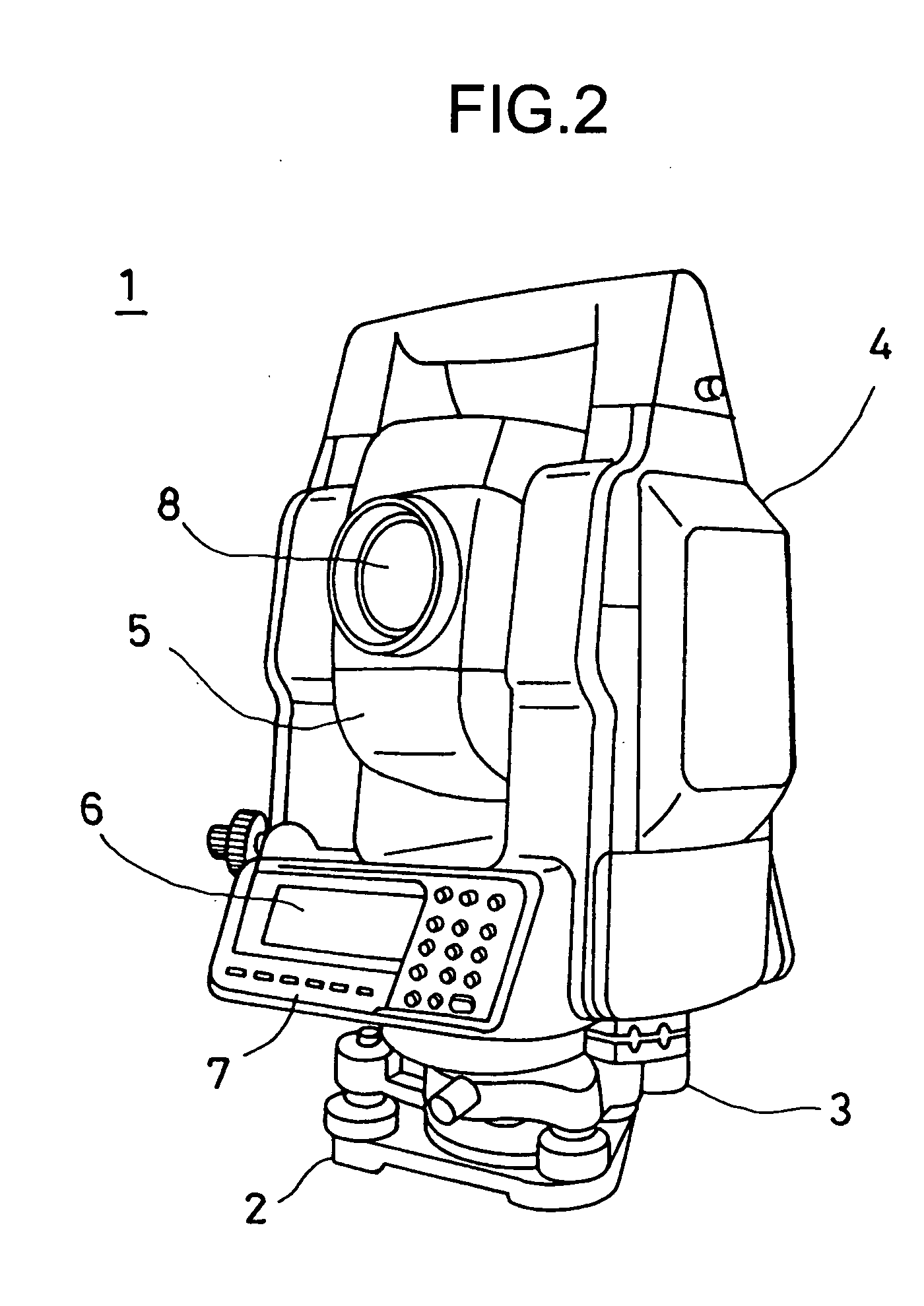
[0025]FIG. 2 shows the surveying instrument 1, to which the present invention is applied. The surveying instrument 1 used is a total station, for instance. A pulsed laser beam is projected to a measuring point. A pulsed reflection light from the measuri...


PUM


Abstract

The present invention provides a surveying system, which comprises a surveying instrument 1 which measures a distance and an angle by projecting a distance measuring light toward a target 12 and can measure a three-dimensional position data of said target and has a function to track the target, and a movable side control device 12 provided on the target side, wherein said surveying instrument has a communication means 15 capable to transmit the three-dimensional position data of the target measured by the surveying instrument to said movable side control device and a first control arithmetic unit 29 for controlling the search of the target by the surveying instrument, wherein said movable side control device has a displacement amount detecting means 38 of the target and a second control arithmetic unit 35 for calculating the displacement amount of the target based on a target detection signal from the displacement amount detecting means and for calculating a target position based on the displacement amount of the target and based on the three-dimensional position data, and in case the surveying instrument cannot track the target, the target position transmitted from the movable side control device is acquired, and the first control arithmetic unit starts searching of the target with the target position as a starting point.

Description

BACKGROUND OF THE INVENTION[0001]The present invention relates to a surveying system, in particular, to a surveying system using a surveying instrument with a tracking function.[0002]As a surveying instrument for measuring a distance, a horizontal angle and a vertical angle, a surveying instrument provided with the tracking function has been known in the past. In this type of the surveying instrument, an object reflector (target) such as a corner cube is collimated by a collimating telescope provided on the surveying instrument. A tracking light is projected from the collimating telescope, and when the target is moved, a reflection light from the target is received and the target can be automatically tracked.[0003]Normally, in a surveying instrument with the tracking function, no operator is assigned on the surveying instrument side, and a surveying operator works on the target side. The target is supported by the surveying operator or the target is supported on a construction machi...

Claims


Application Information

Patent Timeline
Patent Type & Authority Applications(United States)
IPC IPC(8): G01B11/03
CPCE02F3/842E02F9/26G01S17/66G01S7/003G01C15/002G01S17/06
Inventor KUMAGAI, KAORUSAITO, MASAHIRO
Owner KK TOPCON
Why Eureka
Try Eureka