
Floating platform method and apparatus

Active Publication Date: 2009-07-09
FLOAT
View PDF5 Cites 4 Cited by
  • Summary
  • Abstract
  • Description
  • Claims
  • Application Information

AI Technical Summary

Problems solved by technology

Such large area structures are typically tightly coupled by buoyancy to the water surface, and waves can impart undesirable motions and induce undesirable dynamic and static stresses in the structures.
Because concrete structures are susceptible to failure when stressed in certain ways, these structures stresses must be mitigated.

Method used


Image

  • Floating platform method and apparatus
  • Floating platform method and apparatus
  • Floating platform method and apparatus

Examples


Embodiment Construction

[0011]In the following detailed description, reference is made to the accompanying drawings which form a part hereof wherein like numerals designate like parts throughout, and in which is shown by way of illustration specific embodiments in which the invention may be practiced. It is to be understood that other embodiments may be utilized and structural or logical changes may be made without departing from the scope of the present invention. Therefore, the following detailed description is not to be taken in a limiting sense, and the scope of the present invention is defined by the appended claims and their equivalents.

[0012]Embodiments in accordance with the present invention may be particularly beneficial for large area floating platforms, and may provide a floating platform that includes a continuous or semi-continuous, substantially horizontal bottom plate structure that may be substantially parallel and interconnected with a top plate by a plurality of buoyancy members, which m...


PUM


Abstract

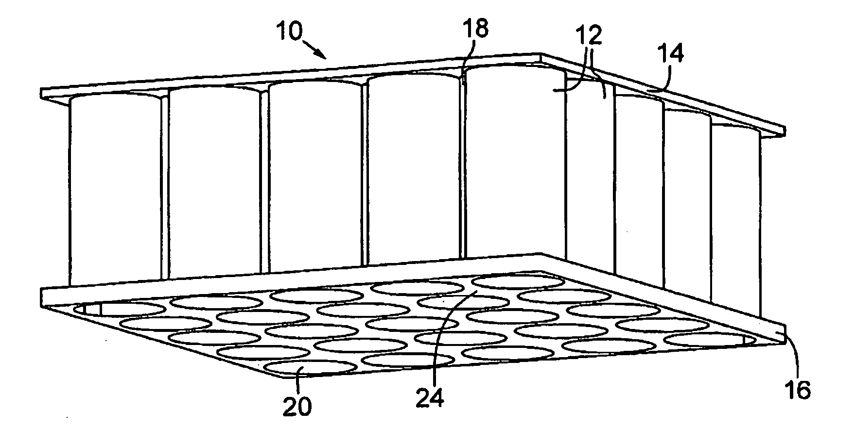
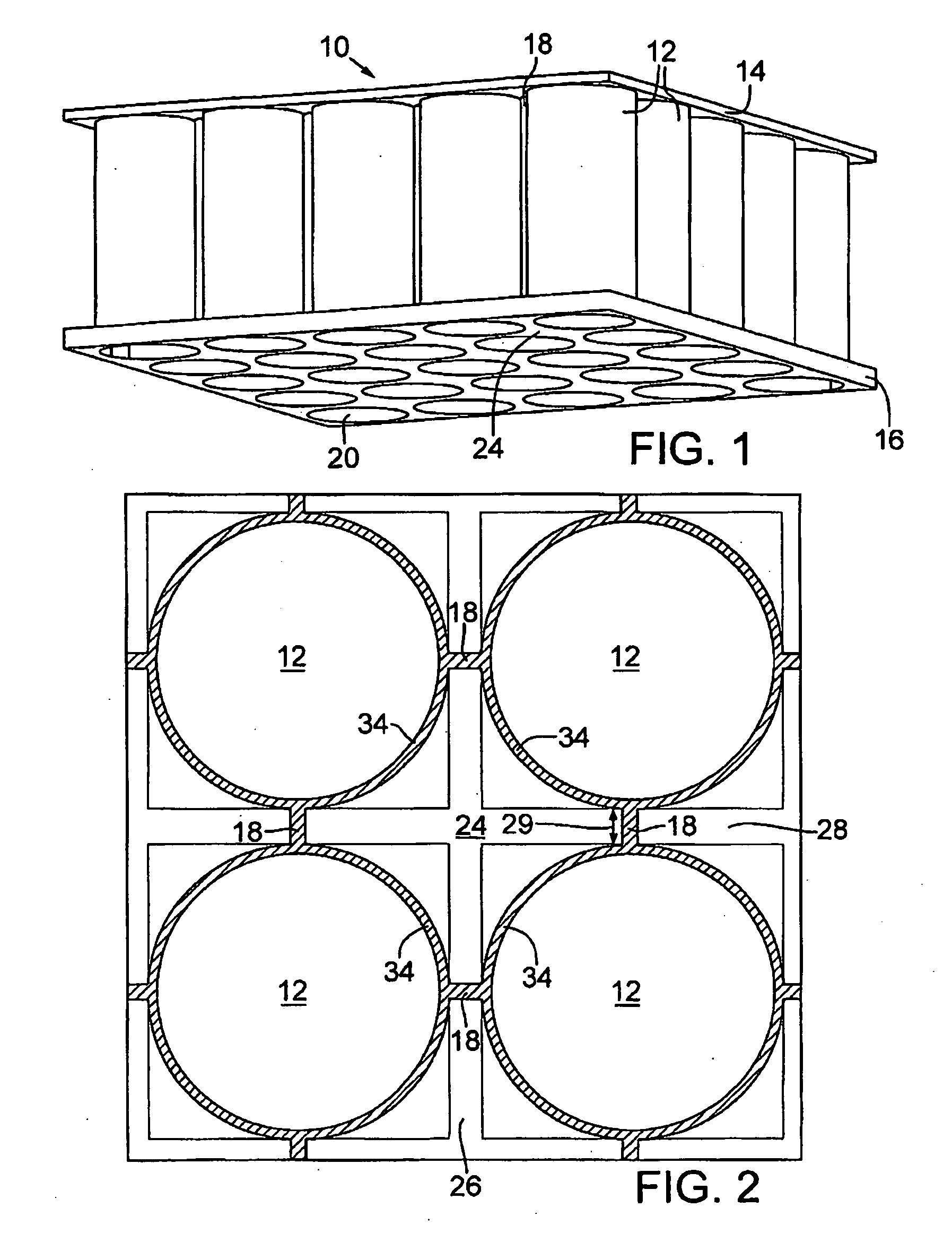
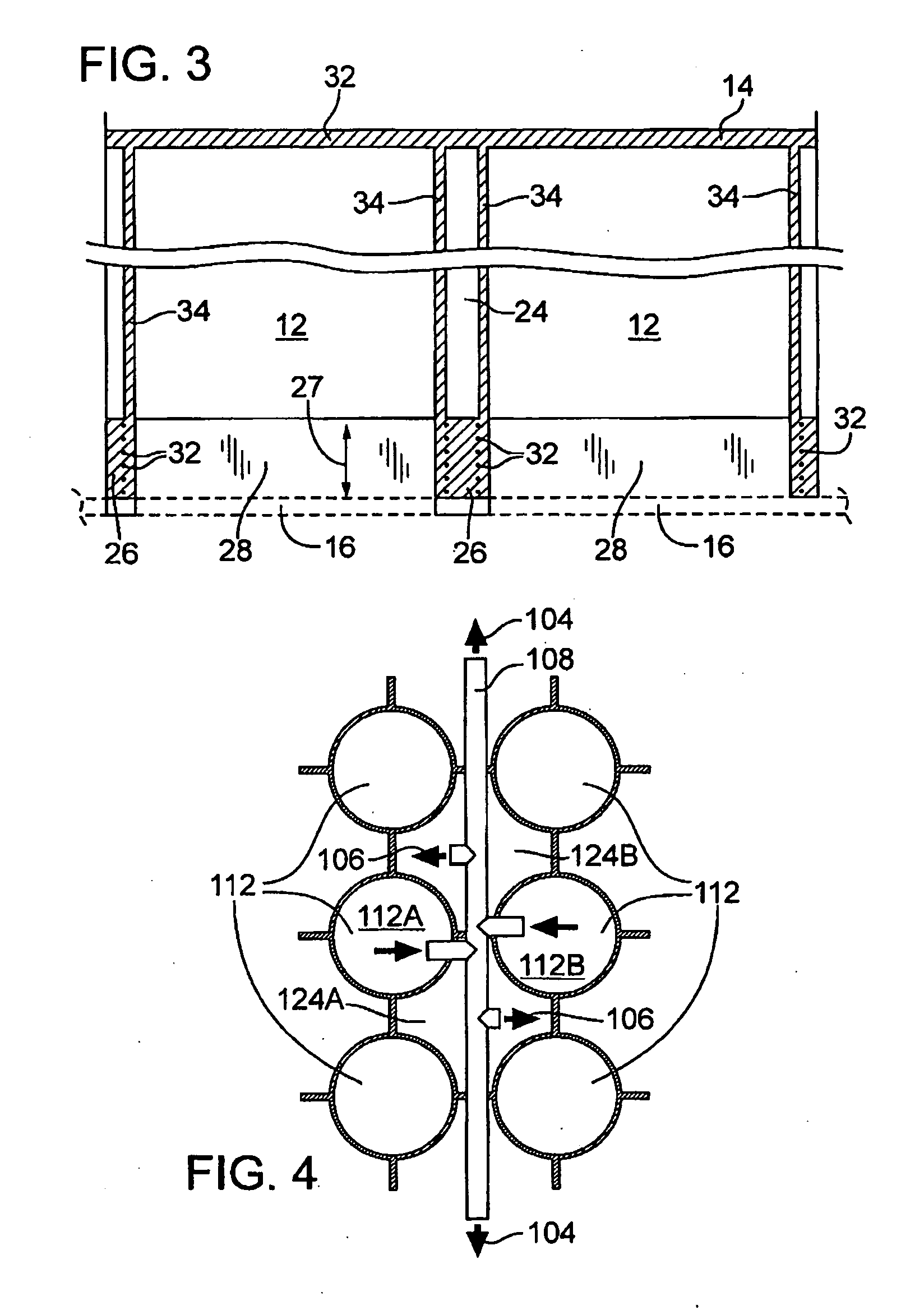
A floating platform is provided. The floating platform includes a top surface (14), a plurality of buoyancy members (12) interconnected to the top surface and extending downwardly into a body of water, a bottom plate (16) and a plurality of interstitial volumes (24) that are sealed at a bottom end by the bottom plate to prevent the flow of water into the interstitial volume.

Description

FIELD OF THE INVENTION[0001]Disclosed embodiments of the invention relate to the field of large floating platforms, and more particularly, embodiments of the invention relate to a floating platform apparatus and configuration for enhanced platform stabilization and structural support.BACKGROUND OF THE INVENTION[0002]Large area floating structures are useful for providing enlarged areas for a number of large scale operations, such as: offshore petroleum drilling, production and storage; liquefied natural gas on-loading and storage, re-gasification, pressurization and off-loading; electric power plants, both hydrocarbon and nuclear fueled; de-salination water plants; airports, seaports, military bases, living accommodations, floating piers, breakwaters, harbors and the like.[0003]Such structures are most economically fabricated in pre-stressed, steel reinforced concrete composites. Such large area structures are typically tightly coupled by buoyancy to the water surface, and waves can...

Claims


Application Information

Patent Timeline
IPC IPC(8): B63B35/44
CPCB63B39/10B63B35/44
Inventor BROWN, NEAL A.INNIS, DONALD A.
Owner FLOAT
Learn More