Unlock instant, AI-driven research and patent intelligence for your innovation.

Signal processing unit

a technology of signal processing and signal processing, applied in the direction of mechanical actuation of burglar alarms, instruments, transmission monitoring, etc., can solve the problems of unresolved trouble due to unfavorable communication, and portion of reply signals, so as to prevent radio wave interference and suppress the influence of transient response

Active Publication Date: 2009-07-09
BROTHER KOGYO KK
View PDF3 Cites 1 Cited by
  • Summary
  • Abstract
  • Description
  • Claims
  • Application Information

AI Technical Summary

Benefits of technology

[0010]A first object of the present invention is to provide a signal processing unit that can execute smooth communication by setting priority among a plurality of communication processings.
[0011]A second object of the present invention is to provide a signal processing unit that can suppress the influence of the transient response.
[0012]A third object of the present invention is to provide a signal processing unit that can easily realize an apparatus for communicating with a RFID tag capable of network connection and can prevent radio wave interference only by being attached to a usual information terminal.

Problems solved by technology

In communication between this apparatus for communicating with a RFID tag and a RFID tag, there is a trouble in which favorable communication is obstructed by influence of transient response.
As an influence of the transient response of a transmission modulation wave in the communication with a RFID tag by an apparatus for communicating with a RFID tag, a modulation degree of a transmission signal (interrogation wave) transmitted from the apparatus for communicating with a RFID tag is larger than that of a reply signal (response wave) returned from the RFID tag, and since a transient response period is overlapped with a return period of the reply signal from the RFID tag, a head portion of the reply signal is crushed by a wrap around signal from the transmission side, which is a trouble.
However, with the prior art described in the JP, A, 2001-53642, such consideration is not given and the trouble due to the influence of the transient response could not be solved.

Method used


Image

  • Signal processing unit
  • Signal processing unit
  • Signal processing unit

Examples


first embodiment

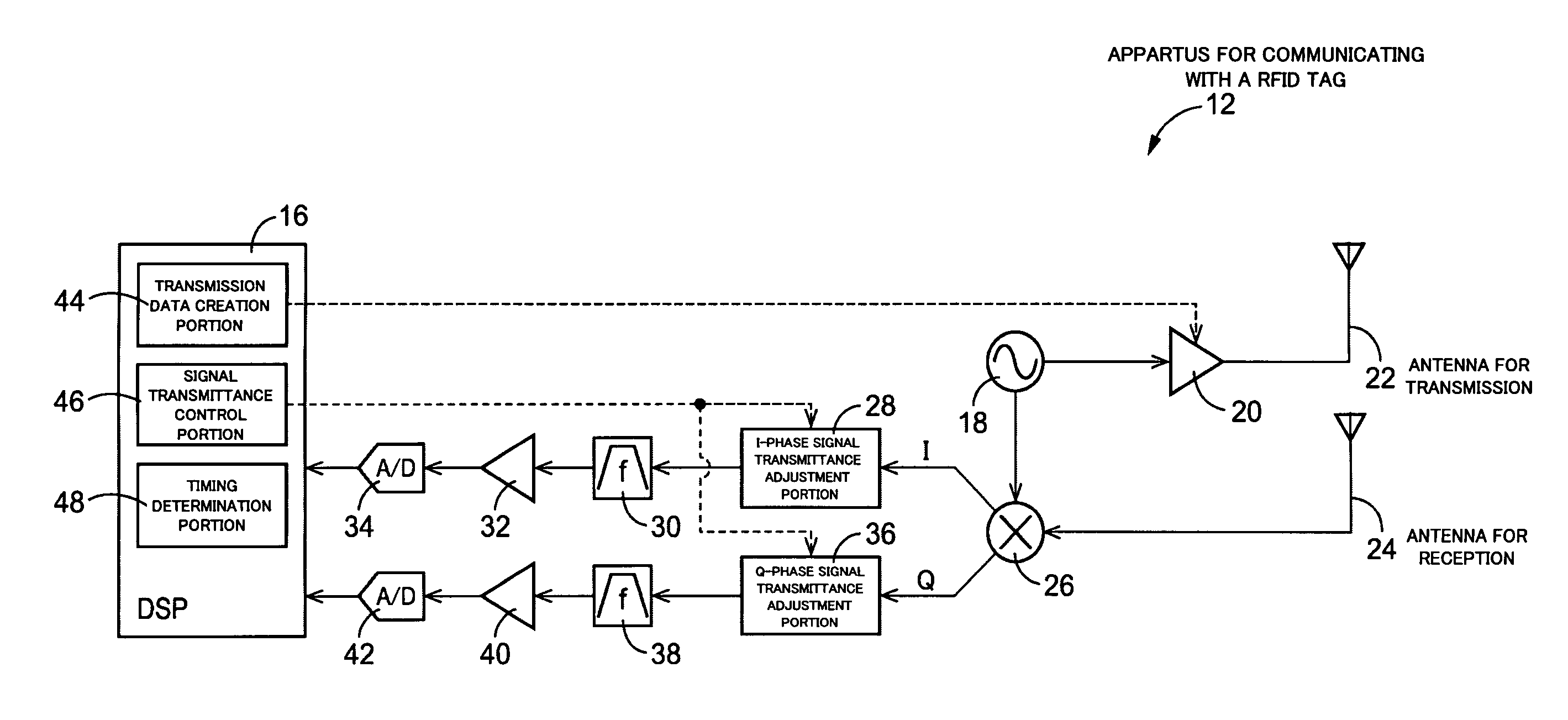
[0032]the present invention will be described referring to FIGS. 1 to 8. This embodiment is an embodiment configured to suppress an influence of transient response.

[0033]FIG. 1 is a diagram for illustrating a RFID tag communication system 10 to which the present invention is favorably applied. The RFID tag communication system 10 is a so-called RFID (Radio Frequency Identification) system configured by an apparatus 12 for communicating with a RFID tag, which is an embodiment of a signal processing unit of the present invention and a single or a plurality of (single in FIG. 1) RFID tags 14, which is a communication target of the apparatus 12 for communicating with a RFID tag, and the apparatus 12 for communicating with a RFID tag functions as an interrogator of the RFID system and the RFID tag 14 as a responder, respectively. That is, when an interrogation wave Fc (transmission signal) is transmitted from the apparatus 12 for communicating with a RFID tag to the RFID tag 14, in the R...


PUM


Abstract

Since signal transmittance adjustment devices that can suppress transmittance of a receiving signal to a DSP as a receiving processing device from an antenna for reception and a signal transmittance control device configured to control the signal transmittance adjustment devices so that the transmittance of the receiving signal to the DSP from the antenna for reception is suppressed at least when a transmission signal including a modulation signal is transmitted from an antenna for transmission are provided, occurrence of a trouble in which a head portion of a reply signal is crushed by a wrap around signal from a transmission side can be suitably prevented, and particularly, favorable communication can be realized at start of a response from a RFID tag. That is, an apparatus for communicating with a RFID tag that can suitably suppress an influence of a transient response can be provided.

Description

CROSS-REFERENCE TO RELATED APPLICATION[0001]This is a CIP application PCT / JP2007 / 068726, filed Sep. 26, 2007, which was not published under PCT article 21(2) in English.BACKGROUND OF THE INVENTION[0002]1. Field of the Invention[0003]The present invention relates to a signal processing unit configured to communicate with a RFID tag which can write in and read out information via radio communication.[0004]2. Description of the Related Art[0005]A RFID (Radio Frequency Identification) system configured to read out information from a small-sized RFID tag (responder) in which predetermined information is stored by a predetermined apparatus for communicating with a RFID tag (signal processing unit) contactlessly is known. Since this RFID system is capable of reading out the information stored in the RFID tag through communication with the apparatus for communicating with a RFID tag even if the RFID tag is stained or positioned in a hidden position, practical use in various fields such as m...

Claims


Application Information

Patent Timeline
IPC IPC(8): H04L25/40G08B13/14
CPCH04B5/0062H04B5/77
Inventor ICHIKAWA, YASUHISANAGAI, TAKUYAHIRATA, HIRONORIOHASHI, TSUYOSHI
Owner BROTHER KOGYO KK