Automatic velocity control treadmill using pressure sensor array and fuzzy-logic

a technology of automatic speed control and speed control, applied in the direction of gymnastic exercise, sport apparatus, cardiovascular exercise devices, etc., can solve the problems of inaccurate control of speed, inconvenient manipulation, and limitations in the application of practical products to achieve accurate calculation

Inactive Publication Date: 2009-07-09
RES COOPERATION FOUND OF YEUNGNAM UNIV
View PDF7 Cites 35 Cited by
  • Summary
  • Abstract
  • Description
  • Claims
  • Application Information

AI Technical Summary

Benefits of technology

[0018]As described above, the present invention automatically controls the speed of a walking belt using pressure sensors, thereby solving the inconvenience in which an exerciser must manually control the speed. Furthermore, the pace speed and exercise center of an exerciser can be accurately calculated using pressure sensors, therefore there is an advantage in that detailed speed control is enabled.

Problems solved by technology

However, in the case where the exerciser manually manipulates the speed of the treadmill using buttons during running exercise, there is inconvenience in manipulation.
However, this apparatus has many limitations to application to practical products in that reflectivity varies with the dress or movement of the body of an exerciser, which is the ultrasonic reflector, so that it is difficult to measure the position of the exerciser and a measured a signal is disturbed, with the result that there are many limitations in the application thereof to practical products.
However, the method of controlling the position of a walking belt using optical sensors has a problem in that speed is inaccurately controlled because only the position of a user's foot is detected using an optical sensor, regardless of whether it is the right or left foot, and then the speed is controlled.
Furthermore, the apparatus has a problem in that the position of a user's foot is not accurately detected when light radiated from the light-emitting units is weak due to a problem, such as an excessive distance between the light-emitting units 15a and the light-receiving units 15b because the light-emitting units 15a and the light-receiving units 15b are disposed on either the left or right sides of the walking belt.

Method used


Image

  • Automatic velocity control treadmill using pressure sensor array and fuzzy-logic
  • Automatic velocity control treadmill using pressure sensor array and fuzzy-logic
  • Automatic velocity control treadmill using pressure sensor array and fuzzy-logic

Examples


Embodiment Construction

[0032]Detailed descriptions of preferred embodiments of the present invention will be given in conjunction with the accompanying drawings below. It should be noted that, in the assignment of reference numerals to the elements of respective drawings, the same elements are made to have the same reference numerals, even though the elements are shown in different drawings. Furthermore, in the description of the present invention, detailed descriptions of well-known functions or constructions will be omitted when it is determined that such descriptions would make the gist of the present invention obscure.

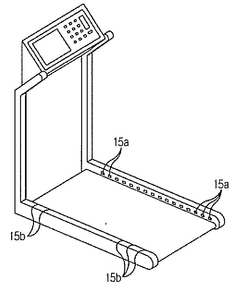
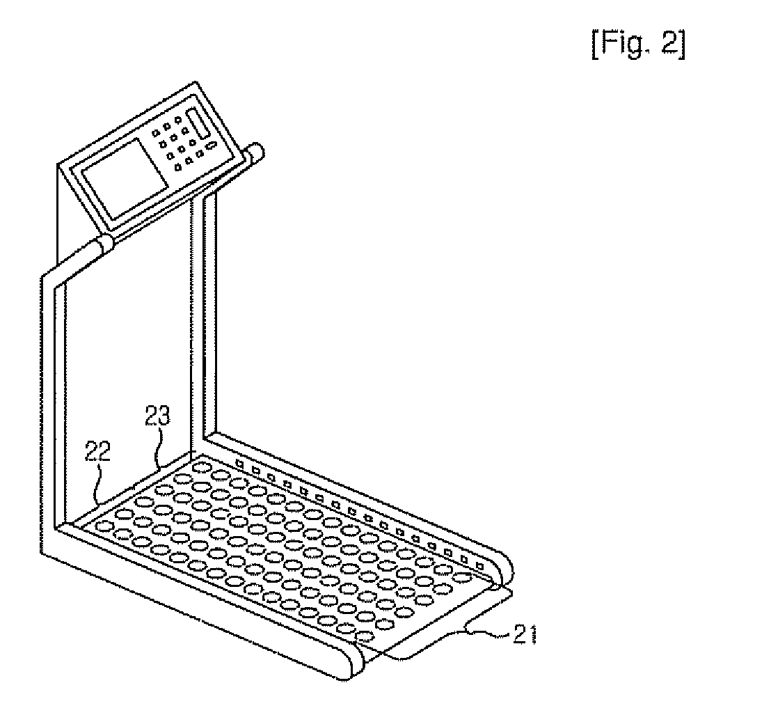
[0033]FIG. 2 is a perspective view showing the appearance of a treadmill in which the speed is controlled using a pressure sensor array according to an embodiment of the present invention.

[0034]Referring to FIG. 2, a pressure sensor array 21 is provided between the bottom surface of the treadmill and a walking belt, and thus can detect the load of an exerciser who takes exercise on the w...


PUM


Abstract

The present invention relates to an automatic speed-controlled treadmill using a pressure sensor array and a method of operating the same. The automatic speed-controlled treadmill includes a walking belt, a pressure sensor array including pressure sensors for detecting loads of the exerciser's feet and outputting the detected loads of the feet as load detection signals, a pace speed status storage unit for storing a pace speed and variation in pace speed of the exerciser, and a control unit provided with an algorithm for calculating a pace speed of the exerciser using the load detection signals, calculating a difference between a previous pace speed and a current pace speed as the variation in pace speed, calculating the exercise center of the exerciser, and proportionally accelerating / decelerating a driving speed of the walking belt in consideration of the variation in pace speed and the exercise center.

Description

TECHNICAL FIELD[0001]The present invention relates to an automatic speed-controlled treadmill that uses a pressure sensor array and a method of operating the same, and has a technical feature such that it detects the load of an exerciser, calculates variation in pace speed and an exercise center, and then automatically controls the driving speed of a walking belt.BACKGROUND ART[0002]In general, a treadmill is exercise equipment that enables running or walking exercise to be performed indoors. As shown in FIG. 1(a), the treadmill includes a walking belt 12, a driving device for moving the walking belt 12, and control means for controlling the driving device. The driving device includes a plurality of rollers for supporting the walking belt 12 and a motor for driving the rollers. The control means controls the driving device in association with the motor. According to such a typical treadmill, a user moves the walking belt 12 by driving the motor through an input module 11, and an exe...

Claims


Application Information

Patent Timeline
Patent Type & Authority Applications(United States)
IPC IPC(8): A63B22/02
CPCA63B22/0242A63B2022/025A63B2024/0093A63B2220/56A63B2220/13A63B2220/30A63B2220/51A63B2220/12A63B22/025A63B22/02
Inventor YI, HWA CHO
Owner RES COOPERATION FOUND OF YEUNGNAM UNIV
Why Eureka
Try Eureka