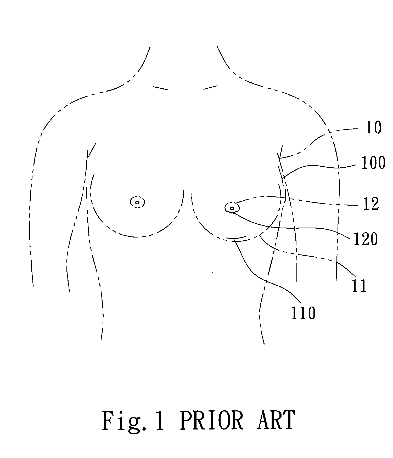
1. The silicon breast implant is quite bulky and difficult to be inserted manually through the incision 100, 110 or 120. The tissues around the incision 100, 110 and 120 easily become rotten and incision enlarged. Scar is hence easily formed and noticeable after operation.
2. The silicon breast implant is inserted forcefully by fingers through the incision 100, 110 or 120, and is possibly damaged. After a period of time the silicon breast implant could be leaking or disrupted to make the breast hardened or deformed, and result in operation failure.
3. By pushing forcefully the silicon breast implant through the incision 100, 110 or 120 with fingers surgeon's fingers could be hurt.
4. To implant the silicon breast implant through the incision 100, 110 or 120 by pushing with fingers,
operation time is longer and results in unfavorable condition to patients.
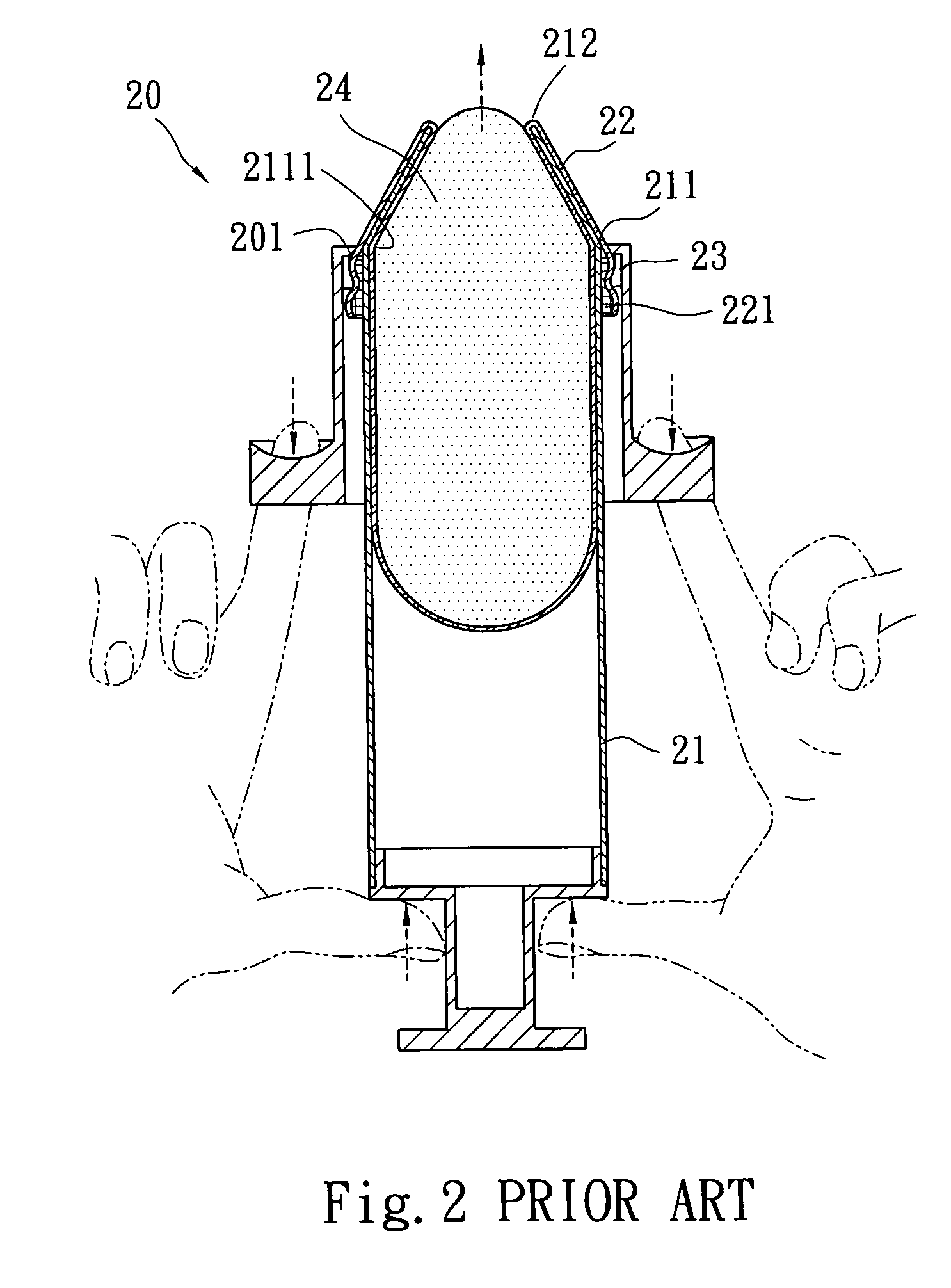
1. The conical opening 212 can only be in inserted in a very shallow location at the
incision site rather than in a proper depth. Unless the incision is made larger for the conical opening
insertion deeper, the breast implant 24 cannot be inserted deeply inside from the incision and into the submammary pocket, thus the implanted breast implant 24 will easily loosens off after
insertion. So that it does not provide much benefits to the operation.
2. The conical opening 212 and the one end 211 of the tube 21 are joined at a location where an unsmooth angular corner 2111 is formed. The angular corner 2111 creates a greater friction to the breast implant 24 and makes pushing out of the breast implant 24 through conical opening 212 difficult.
3. During pushing of the breast implant 24 the outer side of the bag 22 has to be pulled downwards toward the
nozzle 201 by the
injector 20 (referring to the arrow shown in FIG. 2). A great friction and resistance takes place while the bag 22 is located at the conical opening 212. Adding the resistance caused by the angular corner 2111, the bag 22 could be broken, and pushing out of the breast implant 24 is even more difficult.
1. It has a guiding rod 31 which is inserted into the injection barrel 30 through a
tail end and has a front end extended outside an injection opening 32 where twelve pieces of flaps 33 are being extended first. As the twelve flaps 33 are formed by an injection process, they tend to stick together. Hence they have to be extended first by the front of the guiding rod 31 before they are inserted in the incision of a patient to allow the opening 32 to be disposed inside the incision. Then a
plunger 35 with a hard head 351 is pushed forwards through a rear end of the injection barrel 30 as shown in FIG. 4A to inject a breast implant 34 through the opening 32 into a inner side of the breast of the patient for positioning. While the breast implant 34 is pushed and passes through the opening 32, the twelve flaps 33 are pushed by the breast
prosthesis 34 to extend outward and form gaps among them. The breast implant 34 thus tends to be wedged in these gaps and damaged during it's being pushed to pass through the opening 32 (referring to FIG. 4B).
2. The injection barrel 30 gradually forms a tapered portion at the bottom of the opening 32 adjacent to the twelve flaps 33. Unsmooth angular corners 301 and 302 are formed at the junction that become obstacles during pushing of the breast implant 34 by the hard head 351 of the plunger 35 in the injection barrel 30. The breast implant 34 cannot be moved smoothly and clogging could occur. When the breast implant 34 reaches the angular corner 301 at the top end of the barrel and the bottom end of the angular corner 302, a greater
resistance force is formed. As a result moving of the breast implant 34 is difficult.
3. Because of the inadequate design of twelve flaps 33, an extra element of the guiding rod 31 has to be provided. More unnecessary surgical procedure is needed because of this situation.

