Antenna apparatus and adjusting method thereof

a technology of antenna apparatus and adjusting method, which is applied in the direction of loop antenna, ferromagnetic core loop antenna, radiating element structure form, etc., can solve the problems of large number of inferior antenna apparatuses manufactured, the resonant frequency cannot be adjusted during the assembly of the antenna apparatus, so as to achieve the effect of expanding the resonant frequency range of the antenna apparatus

Active Publication Date: 2009-07-16
PANASONIC CORP
View PDF7 Cites 37 Cited by
  • Summary
  • Abstract
  • Description
  • Claims
  • Application Information

AI Technical Summary

Benefits of technology

[0015]In accordance with the present invention, since the second loop pattern is wound in such a manner that the magnetic field is generated from the second loop pattern along the same direction as that of the first loop pattern, the magnetic field generated by the second loop pattern is not canceled by the magnetic field generated from the first loop pattern. As a result, the second loop pattern is cut off, so that the adjusting range of the resonant frequency of the antenna apparatus can be largely expanded, and therefore, occurrences of the adjustment failures of the resonant frequency when the antenna apparatus is assembled can be greatly lowered.

Problems solved by technology

However, in the conventional antenna apparatuses, since the adjusting ranges of the resonant frequencies in the antenna patterns have been made narrow, the resonant frequencies could not be adjusted when these antenna apparatuses were assembled.
As a result, a large number of inferior antenna apparatuses have been manufactured.
However, since the resonant frequencies have been adjusted by changing the turn numbers, the resonant frequencies could not be adjusted during assembling of the antenna apparatuses.
Further, tolerance ranges of center frequencies in antenna apparatuses, which are required from manufacturers of a portable telephone have been narrowed year by year, and therefore, adjusting of resonant frequencies of the antenna apparatuses could be very hardly carried out.

Method used


Image

  • Antenna apparatus and adjusting method thereof
  • Antenna apparatus and adjusting method thereof
  • Antenna apparatus and adjusting method thereof

Examples


embodiment 1

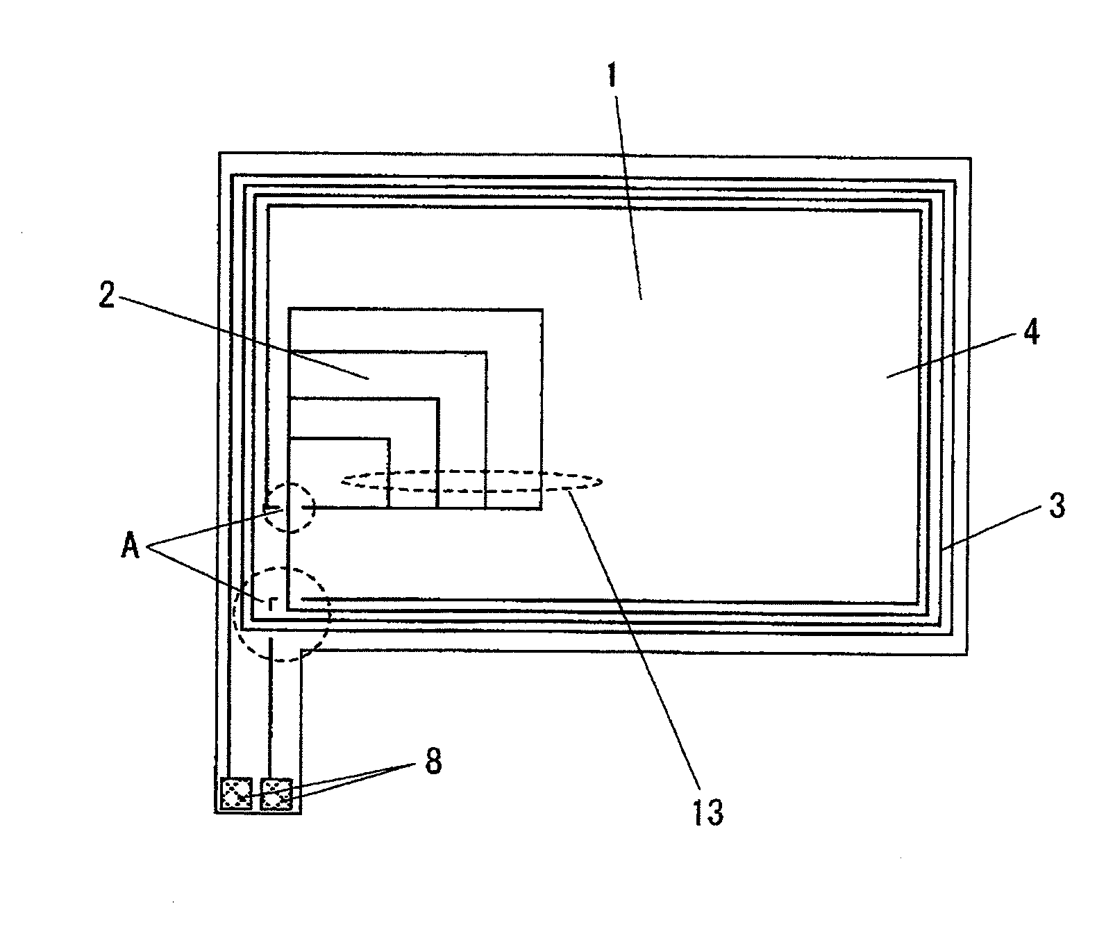
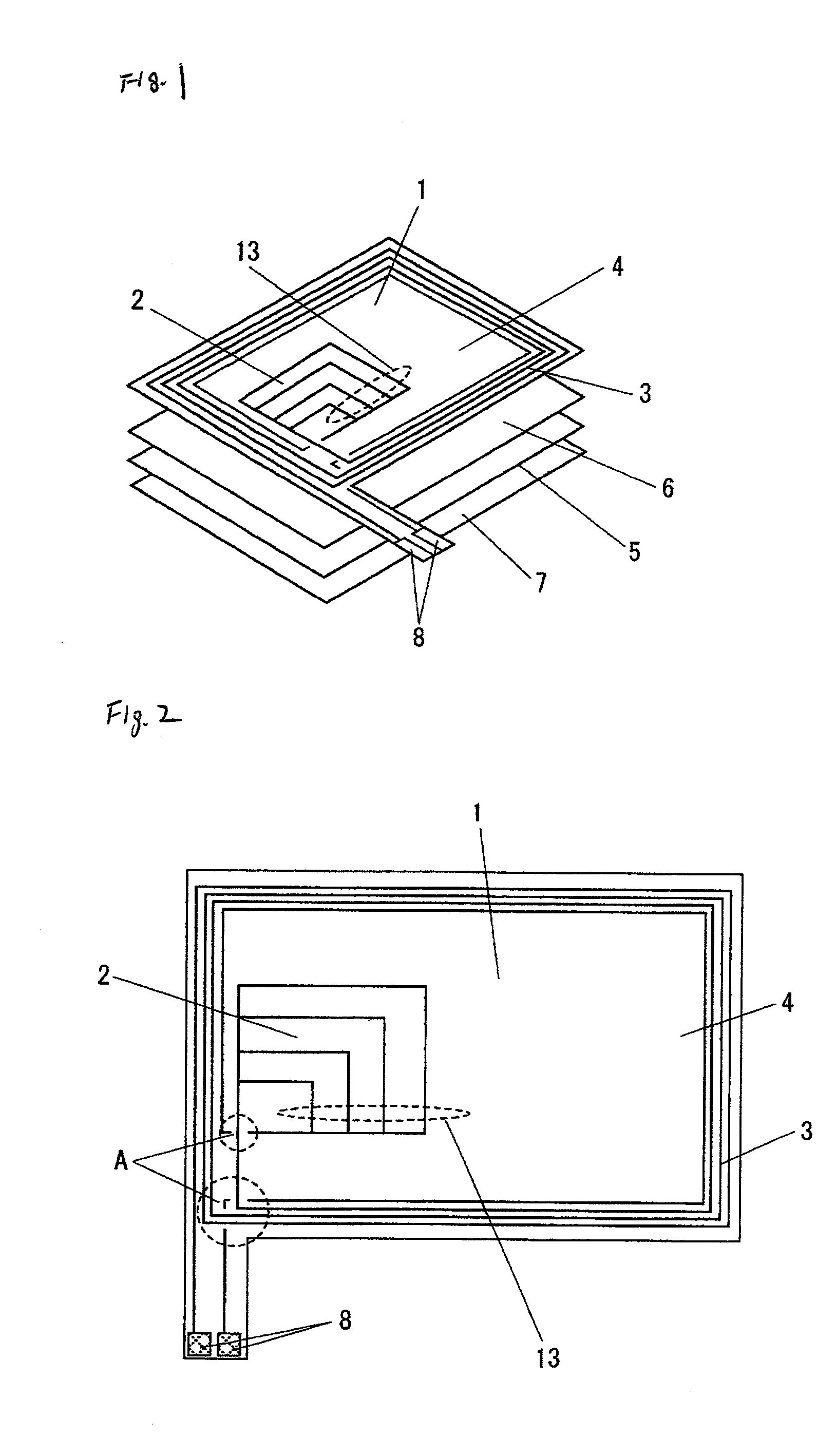
[0027]Firstly, a description is made of a shape and a structure of an antenna apparatus 1 according to an embodiment 1 of the present invention.

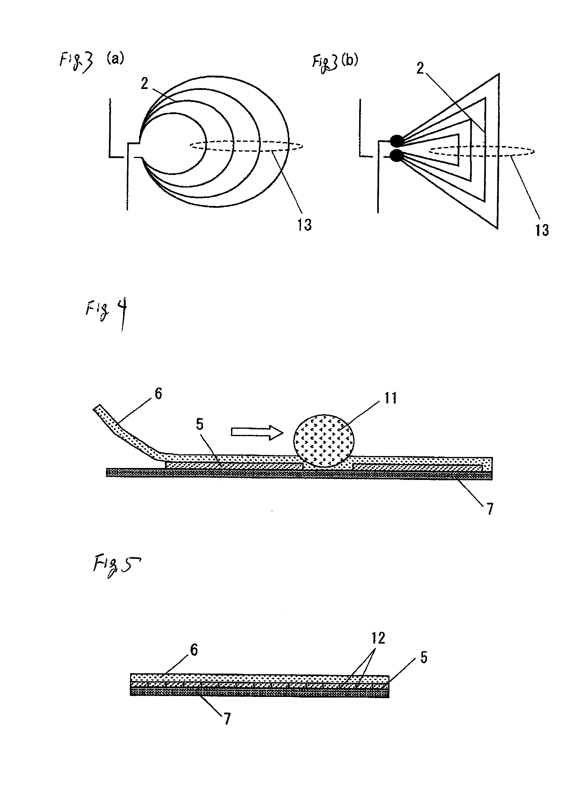
[0028]The antenna apparatus 1 indicated in FIG. 1 has been constructed in such manner that an antenna unit 3 corresponding to a first loop pattern has been formed on a base member 4, and a loop pattern 2 corresponding to a second loop pattern has been formed in a portion of the antenna unit 3. A magnetic seat 5 coated by protection members 6 and 7 has been adhered to an under portion of the base member 4.

[0029]It should also be noted that both the loop pattern 2 and the antenna unit 3 have been wound along a clockwise direction in such a manner that antenna currents may flow along the same direction. As a result, magnetic fields are generated from the loop pattern 2 and the antenna unit 3 along the same direction.

[0030]As a consequence, since the magnetic field generated from the loop pattern 2 is not canceled by the magnetic field generated...

embodiment 2

[0077]An antenna apparatus 1 according to an embodiment 2 of the present invention is featured by that a large-sized loop pattern 2 and a small-sized loop pattern 2 are provided so as to adjust a resonant frequency thereof. It should be noted that structural elements of the antenna apparatus 1 according to the embodiment 2 similar to those of the above-described embodiment 1 will be denoted by the same reference numerals shown in the embodiment 1.

[0078]The antenna apparatus 1 of the embodiment 2 of the present invention has been constructed by employing a base member 4, an antenna unit 3, large-sized and small-sized loop patterns 2, a magnetic seat 5, protection members 6 and 7, and a terminal connecting unit 8.

[0079]The base member 4 has been made of a polyimide substrate. As shown in FIG. 7, while both the antenna unit 3, and the large-sized and small-sized loop patterns 2 have been provided on the base member 4, the large-sized and small-sized loop patterns 2 have been formed at ...

embodiment 3

[0088]An antenna apparatus 1 according to an embodiment 3 of the present invention is featured by that a loop pattern 2 and a ladder-shaped pattern 9 are combined with each other so as to adjust a resonant frequency thereof. It should be noted that structural elements of the antenna apparatus 1 according to the embodiment 3 similar to those of the above-described embodiment 1 will be denoted by the same reference numerals shown in the embodiment 1.

[0089]The antenna apparatus 1 of the embodiment 3 of the present invention has been constructed by employing a base member 4, an antenna unit 3, the loop pattern 2, the ladder-shaped pattern 9, a magnetic seat 5, protection members 6 and 7, and a terminal connecting unit 8.

[0090]The base member 4 has been made of a polyimide substrate. As shown in FIG. 8, while both the antenna unit 3, the loop pattern 2, and the ladder-shaped pattern 9 have been provided on the base member 4, the loop pattern 2 has been formed at a center portion of a lef...


PUM


Abstract

An antenna apparatus is featured by that a base member 4 has an antenna unit 3 and a loop pattern 2 wound in such a manner that a magnetic field of the loop pattern 2 is generated along the same direction as that of the antenna unit 2, and the loop pattern 2 has been formed by a plurality of loops connected parallel to each other.

Description

BACKGROUND[0001]1. Field of the Invention[0002]The present invention generally relates to an antenna apparatus which is employed in a wireless communication medium processing apparatus communicated with a wireless communication medium such as an RFID (Radio Frequency Identification), namely, an IC card, an IC tag, and the like, or which is employed in the wireless communication medium itself. More specifically, the present invention is directed to such an antenna apparatus which can be made thin and in low cost and can improve a communication characteristic thereof in a microwave system, and an electromagnetic induction system, and also, is directed to an adjusting method thereof.[0003]2. Description of the Related Art[0004]Conventionally, in an RFID medium, namely, a non-contact type IC card, or an IC tag, in such a case that an antenna characteristic thereof is adjusted, as represented in FIG. 10, the following adjusting operation has been performed. That is, a capacitor pattern 1...

Claims


Application Information

Patent Timeline
Patent Type & Authority Applications(United States)
IPC IPC(8): H01Q7/06
CPCH01Q7/06
Inventor NAKAMURA, KOUICHIKIYOSUE, KUNIAKITANIGUCHI, KENJIKOBAYASHI, NAOYUKI
Owner PANASONIC CORP
Why Eureka
Try Eureka