

Image Shooting Apparatus and Blur Correction Method
a technology of image shooting and blur correction, applied in the field of image shooting apparatus, to achieve the effect of reducing nois
- Summary
- Abstract
- Description
- Claims
- Application Information
AI Technical Summary
Benefits of technology
Problems solved by technology
Method used
Image

Examples
first embodiment
[0084]Now a first embodiment of the invention will be described. Usually a short-exposure image contains a smaller degree of blur than an ordinary-exposure image; thus, by correcting an ordinary-exposure image with the aim set for the edge condition of a short-exposure image, it is possible to reduce blur in the ordinary-exposure image. To obtain a sufficient blur correction effect, however, it is necessary to give a short-exposure image an adequately high signal-to-noise ratio (hereinafter referred to as “S / N ratio”). In actual shooting, however, it may be impossible to shoot a short-exposure image that permits a sufficient blur correction effect. In such a case, forcibly performing short-exposure shooting and blur correction processing does not produce a satisfactory blur correction effect (even a corrupted image may be generated). With these circumstances taken into consideration, in the first embodiment, whenever it is judged that it is impossible to acquire a short-exposure ima...
second embodiment
[0117]Next, a second embodiment of the invention will be described. Part of the operation described in connection with the first embodiment is used in the second embodiment as well. With reference to FIG. 7, the shooting and correction operation of the image shooting apparatus 1 according to the second embodiment will be described. FIG. 7 is a flow chart showing the flow of the operation. Also in the second embodiment, first, the processing in steps S1 through S4 is performed. The processing in steps S1 through S4 here is the same as that described in connection with the first embodiment.
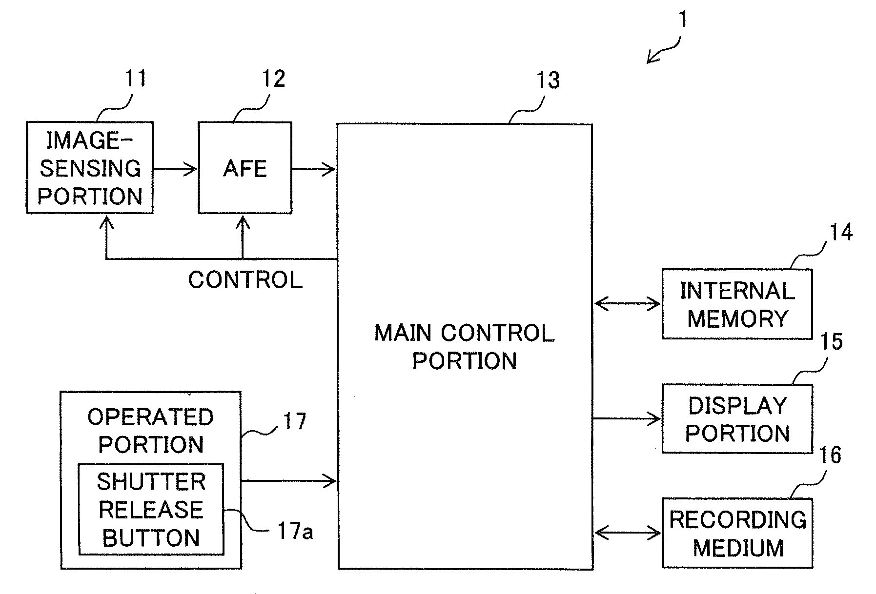
[0118]Specifically, when the shutter release button 17a is brought into the halfway pressed state, the shooting control portion 51 acquires the shooting parameters of an ordinary-exposure image (the focal length f1, the exposure time t1, and the ISO sensitivity is1). Thereafter, when the shutter release button 17a is brought into the fully pressed state, in step S4, by use of those shooting paramete...
third embodiment
[0143]Next, a third embodiment of the invention will be described. When a short-exposure image containing a negligibly small degree of blur is acquired, by correcting an ordinary-exposure image with the aim set for the edge condition of the short-exposure image, it is possible to obtain a sufficient blur correction effect. However, even when the exposure time of the short-exposure image is so set as to obtain such a short-exposure image, in reality, depending on the shooting skill of the photographer and other factors, the short-exposure image may contain a non-negligible degree of blur. In such a case, even when blur correction processing based on the short-exposure image is performed, it is difficult to obtain a satisfactory blur correction effect (even a corrupted image may result).
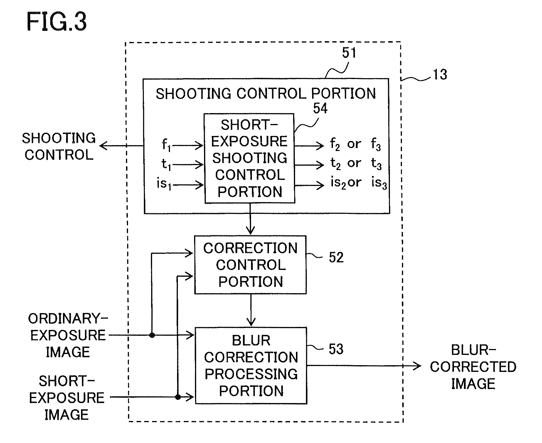
[0144]In view of this, in the third embodiment, the correction control portion 52 in FIG. 3 estimates, based on an ordinary-exposure image and a short-exposure image, the degree of blur contained in th...
PUM
 Abstract
Description
Claims
Application Information