Split field inspection system using small catadioptric objectives
What is Al technical title?
Al technical title is built by PatSnap Al team. It summarizes the technical point description of the patent document.
a catadioptric objective and split field technology, applied in the field of optical imaging, can solve the problems of limited system based on refractive objectives, difficult design of uv objectives with nas (number of apertures) larger than 0.9, and limited catadioptric objectives
Inactive Publication Date: 2009-07-16
KLA TENCOR TECH CORP
View PDF8 Cites 160 Cited by
Summary
Abstract
Description
Claims
Application Information
AI Technical Summary
This helps you quickly interpret patents by identifying the three key elements:
Problems solved by technology
Method used
Benefits of technology
Problems solved by technology
Systems based on refractive objectives are limited due to imaging performance being typically capped in the presence of light energy transmitted at wavelengths above 365 nm.
Design of UV objectives having good correction over fields larger than 100 microns with NAs (numerical apertures) larger than 0.9 has also been difficult.
These large catadioptric objectives have limitations including high cost, tight manufacturing tolerances, inflexible system architectures, and difficulty controlling contamination associated with DUV illumination.
Many of the aforementioned imaging systems have been constructed of relatively large components, which are difficult or impossible to employ in small environments, such as microscopes and the like.
In addition, because of their large size, using multiple objectives in the same system is not practical.
However, smaller inspection objectives than have been typically available have been developed.
The system disclosed in the '850 application offers certain imaging components and arrangements for inspecting specimens, but the designs disclosed therein cannot simply be used in all environments for imaging different types of specimens.
Inspection systems using different geometries, different light sources, with different performance criteria cannot use the designs of the '850 application to accurately and adequately assess specimen flaws under all circumstances.
Method used
Image
Click on the blue label to locate the original text in one second.
Reading with bidirectional positioning of images and text.
Examples
Embodiment Construction
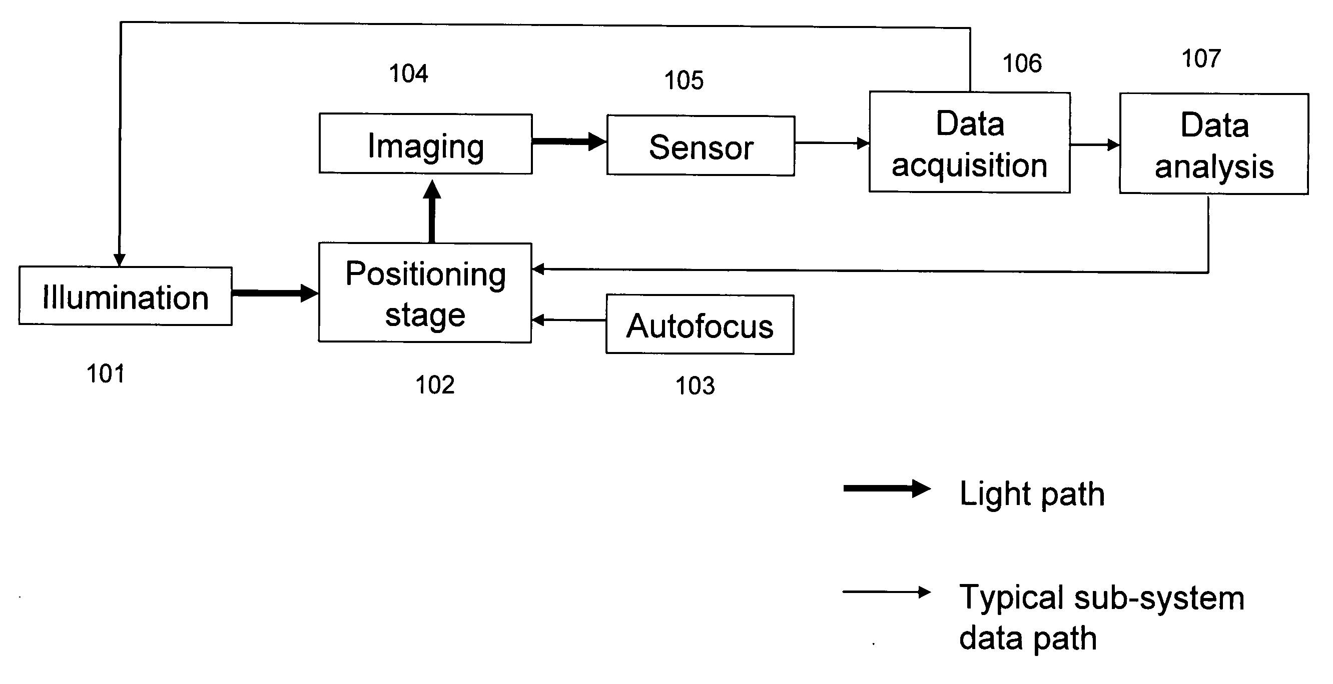
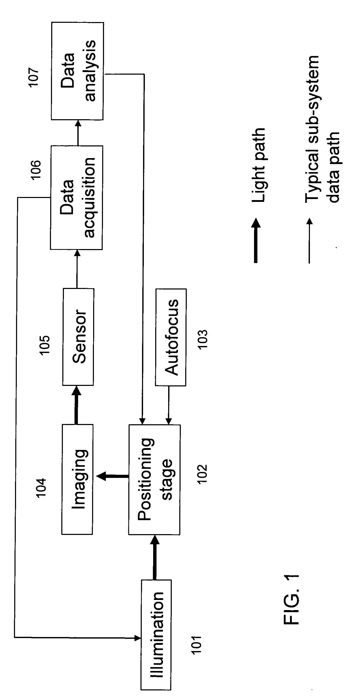
[0019]The inspection systems currently available are highly complex, requiring a sophisticated combination of light source, illumination, imaging, positioning, automatic focusing, image sensor, data acquisition, and data analysis subsystems. New optical designs can enable new inspection system architectures with improved performance, features, and flexibility.
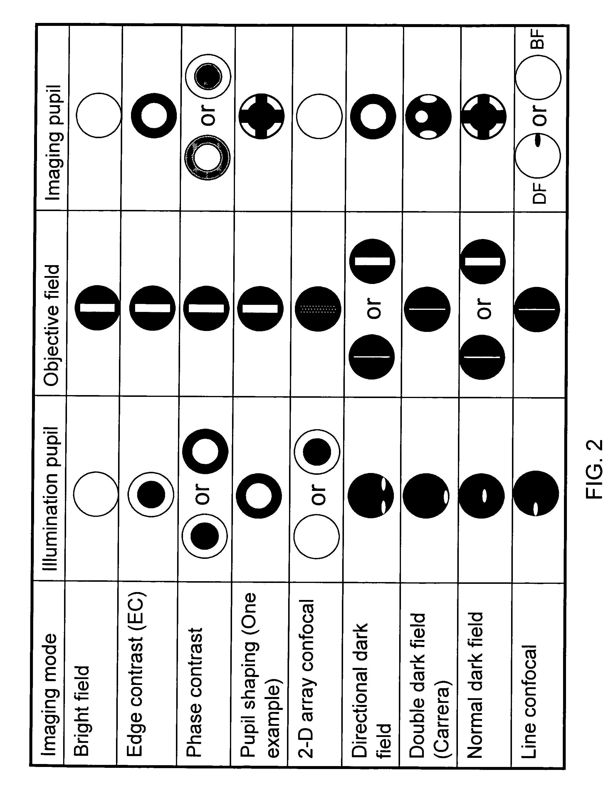
[0020]The development of small sized catadioptric objectives that support ultra-high NA narrow band imaging has enabled improvements to existing inspection system architectures. Use of small objectives enables shorter wavelength inspection than possible using standard refractive based systems. The ultra-high NA designs enable a range of different inspection modes to be implemented as well as allowing different inspection modes to be used simultaneously. In addition, the ultra-high NA provides reduced interference effects from multiple layers on samples and increases the available light for faster inspection speeds.
[0021]An insp...
PUM
Abstract
A system for inspecting a specimen is provided. The system includes an illumination subsystem configured to produce a plurality of channels of light energy, each channel of light energy produced having differing characteristics (type, wavelength, etc.) from at least one other channel of light energy. Optics are configured to receive the plurality of channels of light energy and combine them into a spatially separated combined light energy beam and direct it toward the specimen. A data acquisition subsystem comprising at least one detector is provided, configured to separate reflected light energy into a plurality of received channels corresponding to the plurality of channels of light energy and detect the received channels.
Description
[0001]This application claims the benefit of U.S. Provisional Patent Application Ser. No. 61 / 069,997, entitled “Split Field Inspection System Using Small Catadioptric Objectives,” filed Mar. 18, 2008, which is a continuation-in-part of currently pending U.S. patent application Ser. No. 11 / 543,519, filed Oct. 4, 2006, entitled “High Performance Catadioptric Imaging System,” inventors Shafer et. al., which is a continuation of U.S. patent application Ser. No. 10 / 434,374, now U.S. Pat. No. 7,180,658, filed May 7, 2003, entitled “High Performance Catadioptric Imaging System,” inventors Shafer et. al., which claims the benefit of U.S. Provisional Patent Application Ser. No. 60 / 449,326, entitled “High Performance, Low Cost Catadioptric Imaging System,” filed Feb. 21, 2003.BACKGROUND OF THE INVENTION[0002]1. Field of the Invention[0003]The present invention relates generally to the field of optical imaging and more particularly to optical systems for microscopic imaging, inspection and / or ...
Claims
Application Information
Patent Timeline
Application Date:The date an application was filed.
Publication Date:The date a patent or application was officially published.
First Publication Date:The earliest publication date of a patent with the same application number.
Issue Date:Publication date of the patent grant document.
PCT Entry Date:The Entry date of PCT National Phase.
Estimated Expiry Date:The statutory expiry date of a patent right according to the Patent Law, and it is the longest term of protection that the patent right can achieve without the termination of the patent right due to other reasons(Term extension factor has been taken into account ).
Invalid Date:Actual expiry date is based on effective date or publication date of legal transaction data of invalid patent.
Patent Type & Authority Applications(United States)