Rotary pressure transfer device

a technology of pressure transfer device and rotary device, which is applied in the direction of pump, pump, and pump body, etc., can solve the problem that the rotary device will potentially pump

Active Publication Date: 2009-07-16
ENERGY RECOVERY INC
View PDF14 Cites 87 Cited by
  • Summary
  • Abstract
  • Description
  • Claims
  • Application Information

AI Technical Summary

Benefits of technology

[0012]It has now been found that it is practical to employ two or more inlets and two or more outlets in each end cover, arranging them so that each channel will fill at least twice at each end while accordingly discharging at least twice at the opposite end. As a result, such a rotary device will potentially pump, i.e. increase the pressure of, a liquid volume at least about twice as large during each revolution than similar prior art device with only a single inlet in each end cover.

Problems solved by technology

As a result, such a rotary device will potentially pump, i.e. increase the pressure of, a liquid volume at least about twice as large during each revolution than similar prior art device with only a single inlet in each end cover.

Method used


Image

  • Rotary pressure transfer device
  • Rotary pressure transfer device
  • Rotary pressure transfer device

Examples


Embodiment Construction

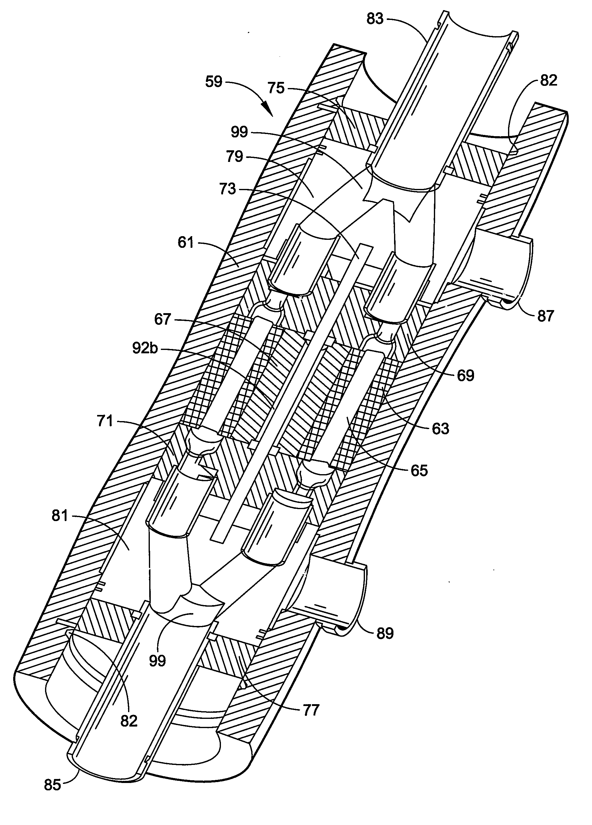
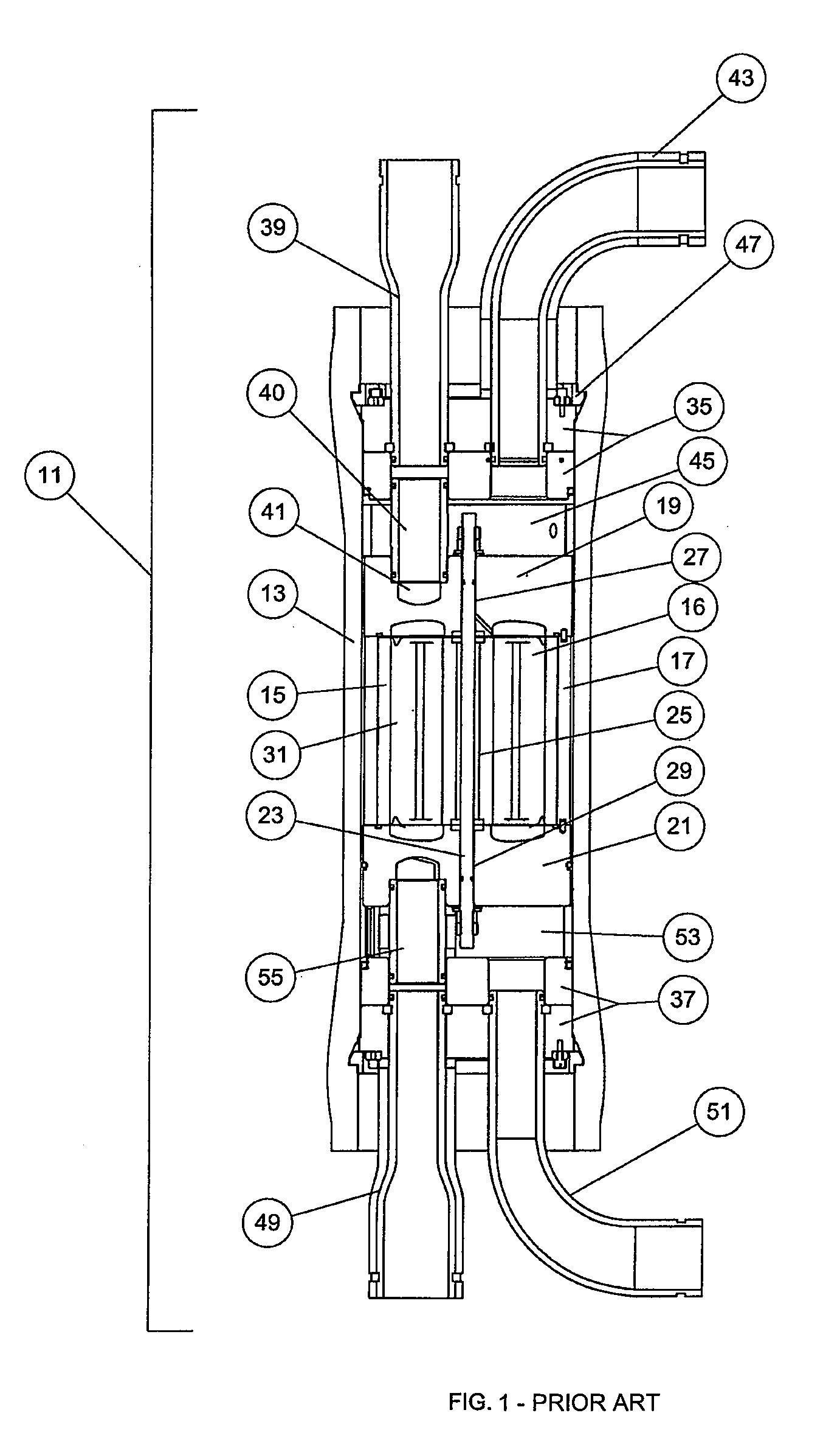
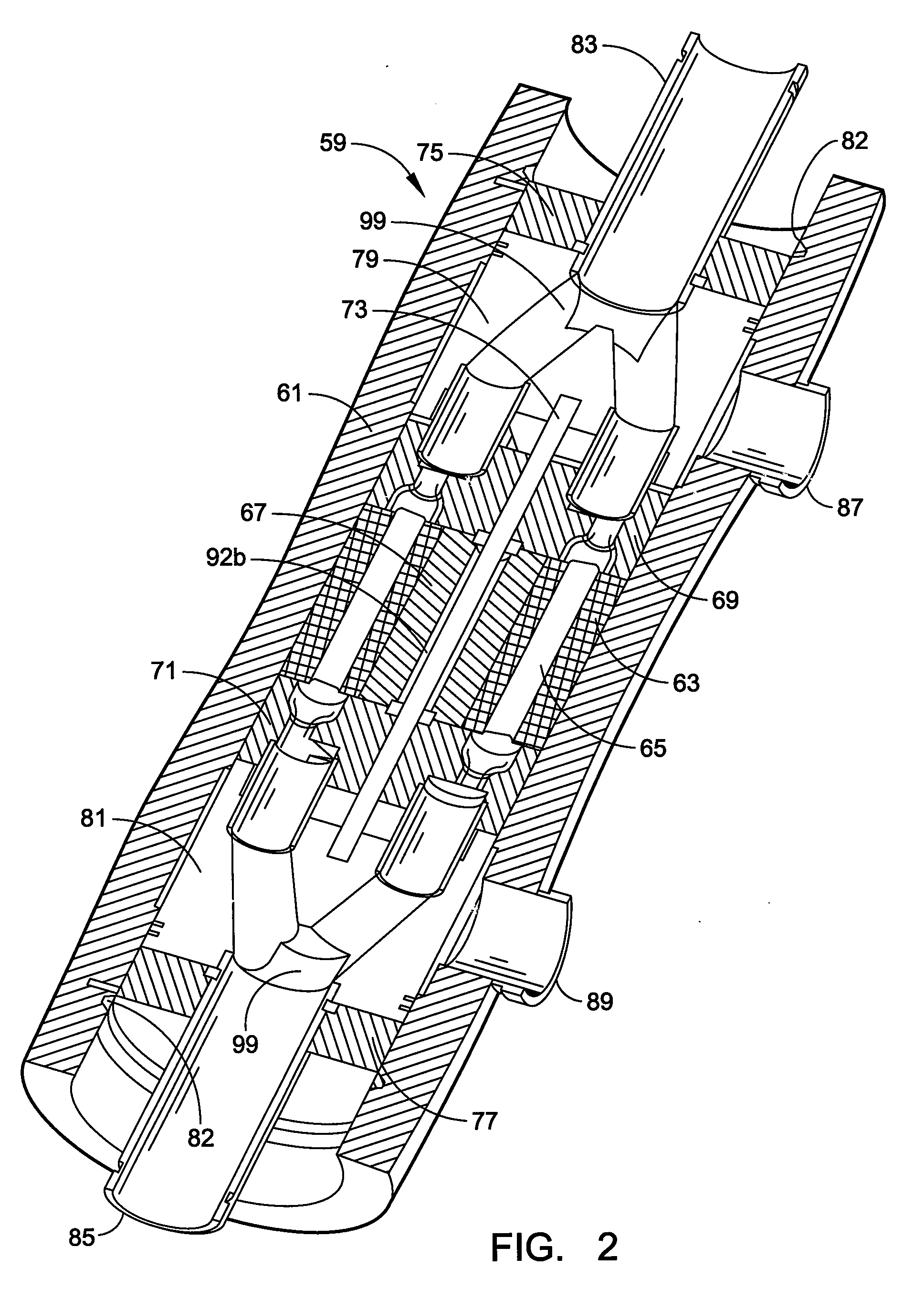
[0019]Shown in FIG. 1 is a rotary pressure transfer device 11 of the general type of those of the prior art that includes an elongated, generally cylindrical housing or body 13 in which there is disposed a cylindrical rotor 15 having a plurality of longitudinal channels 16 which extend end-to-end and open onto the respective end faces of the rotor. The rotor 15 revolves within a surrounding tubular sleeve 17, and two end covers 19, 21 having inlet and outlet openings respectively close the otherwise open ends of the tubular sleeve. For purposes of convenience of explanation, the components are referred to as upper and lower end covers in accordance with the orientation of the device in the drawing. However, such is merely used for convenience as it should be understood that the device may be operated in any orientation, vertical, horizontal or otherwise. To permit these internal components to be handled as a unit, they are often united as a subassembly through the use of a central r...


PUM


Abstract

A pressure transfer device for the transfer of pressure energy from a high pressure fluid stream to a lower pressure fluid stream wherein a generally cylindrical housing (61) contains a rotor (63) having a plurality of channels (65) extending axially therethrough that revolves about a central stator (67) or within a surrounding sleeve (73) and a pair of end covers (69, 71) which slidingly and sealingly interface with respective planar end faces (68) of the rotor. The end covers (69, 71) and the accompanying components of the device are constructed so as to allow the channels to be at least twice filled with a high pressure first liquid during each revolution of the rotor and thus discharge twice the volume of a pressurized second liquid than if they were filled only one with high pressure liquid.

Description

[0001]This application is a continuation of International Application No. PCT / US2007 / 079674 filed Sep. 27, 2007, which claims priority from U.S. Provisional Patent Application Ser. No. 60 / 828,175 filed Oct. 4, 2006, the disclosures of both of which are incorporated herein by reference.FIELD OF THE INVENTION[0002]The invention relates to rotary pressure transfer devices where a first fluid under a high pressure hydraulically communicates with a second, lower pressure fluid in a rotor and transfers pressure between the fluids producing a high pressure discharge stream of the second fluid. More particularly, the invention relates to rotary pressure transfer devices wherein end cover designs and associated rotor arrangements are improved to increase efficiency.BACKGROUND OF INVENTION[0003]Many industrial processes, especially chemical processes, operate at elevated pressures. These processes often require a high pressure fluid feed, which may be a gas, a liquid or a slurry, to produce a...

Claims


Application Information

Patent Timeline
Patent Type & Authority Applications(United States)
IPC IPC(8): F04B17/00F04F99/00F04F13/00
CPCF04F13/00B01D61/06B01D2313/246B01D61/10C02F1/441C02F2303/10C02F2103/08
Inventor MARTIN, JEREMYSTOVER, RICHARD L.
Owner ENERGY RECOVERY INC
Why Eureka
Try Eureka