Cavity-type vacuum sealing machine

a vacuum sealing machine and vacuum technology, applied in machines/engines, positive displacement liquid engines, transportation and packaging, etc., can solve the problems of high cost and large volume, inability to package products containing high liquid or pure liquid products, complex structure, etc., to achieve stable working, reduce the whole volume of the machine, and simple structure

Active Publication Date: 2017-09-19
BIGLAND ELECTRIC APPLIANCE
View PDF13 Cites 1 Cited by
  • Summary
  • Abstract
  • Description
  • Claims
  • Application Information

AI Technical Summary

Benefits of technology

[0004]The utility model overcomes the shortcomings of the prior art and provides a cavity-type vacuum sealing machine, which has the advantages of simple structure, low cost, small volume, saved occupation space and capability of packaging liquid-containing products.
[0017]According to the cavity-type vacuum sealing machine disclosed by the utility model, the vacuum pump set is utilized and the use of a big vacuum pump is avoided, so that the whole volume of the machine is reduced; the vacuum pump set consists of the small vacuum pumps; one driver is utilized to drive four air pumps to work synchronously; the vacuum pump set has the advantages of simple structure, stable working and capability of continuously pumping air; one driver is utilized to drive four air pumps to work, so that the working efficiency is higher; the pumping pressure is boosted, the vacuum degree is increased and the vacuum sealing machine has a plurality of suction ports and exhaust ports; the tube connection of the suction ports and the exhaust ports can be changed according to the required pumping pressure and the pumping speed, and the vacuum sealing machine has wider scope of application. The pumping pressure and the pumping speed can be achieved through different tube connections; and the vacuum sealing machine has the advantages of smaller volume, light weight, small occupation space and low cost and is suitable for families and small workshops.
[0018]The tray with the oblique bottom side is arranged; the tray enables the liquid in the packaging bag to flow toward the bag bottom and prevents the sealing effect from being influenced by too much liquid attached on the mouth of the bag. Furthermore, the hot-pressing bar and the heating and sealing component are capable of evaporating a small amount of liquid at the mouth of the bag, and the sealing effect of the vacuum sealing machine to the packaging bags is further guaranteed.

Problems solved by technology

However, the prior cavity-type vacuum sealing machine is only used in the large production occasions such as factories; and the vacuum sealing machine utilizes a large vacuum pump, has the disadvantages of complex structure, high cost and large volume and is not suitable for household use.
The prior small vacuum sealing machine for household use is just the direct pump type, which is incapable of packaging products containing high liquid or pure liquid products and does not meet the household requirements of packaging products containing high liquid or pure liquid products.
The prior household vacuum sealing machine has smaller volume and generally employs a small vacuum pump; the vacuum pump utilizes a direct-current motor and has one suction port and one exhaust port; the vacuum pump has slow pumping speed and low pumping pressure, which results in lower pumping efficiency and may result in too much air remained in the packaging bag, so that the shelf life of food in the packaging bag cannot be guaranteed.
In addition, the current occasions such as factories generally utilize the large vacuum sealing machine, which utilizes a large vacuum pump or a rotary-vane vacuum pump and uses a large alternating current motor; although the vacuum pump has high pumping speed and high pumping pressure, it has large volume and high cost and is not suitable for families and small sites.

Method used


Image

  • Cavity-type vacuum sealing machine
  • Cavity-type vacuum sealing machine
  • Cavity-type vacuum sealing machine

Examples


Embodiment Construction

[0028]To facilitate the understanding of the technicians in the field, the utility model is further described with the following drawings.

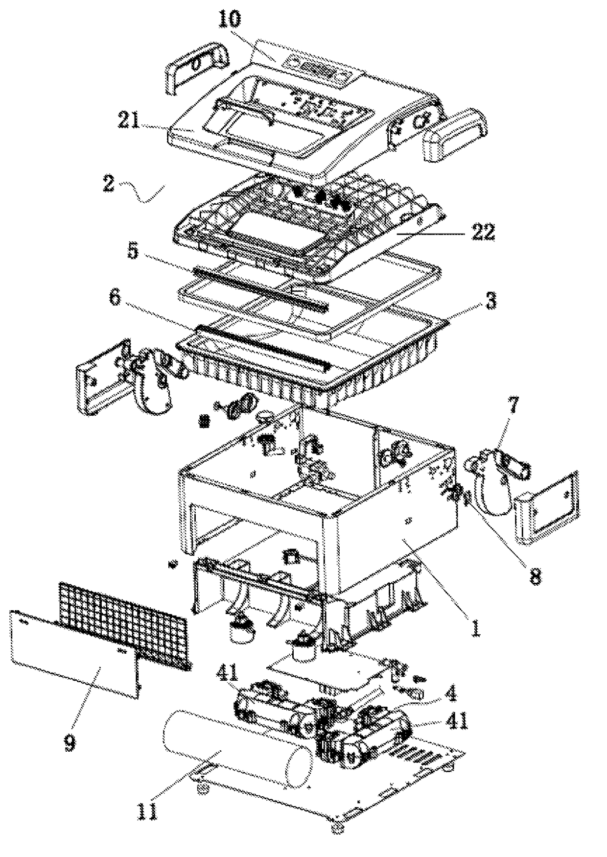
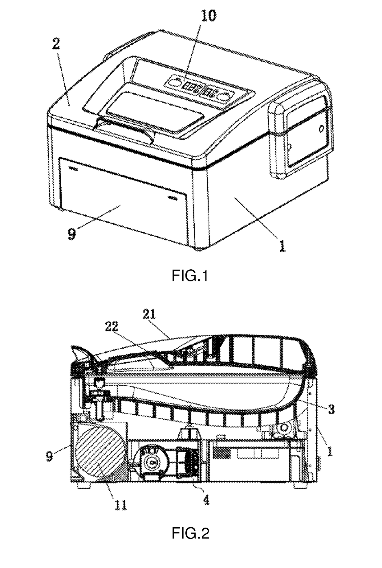
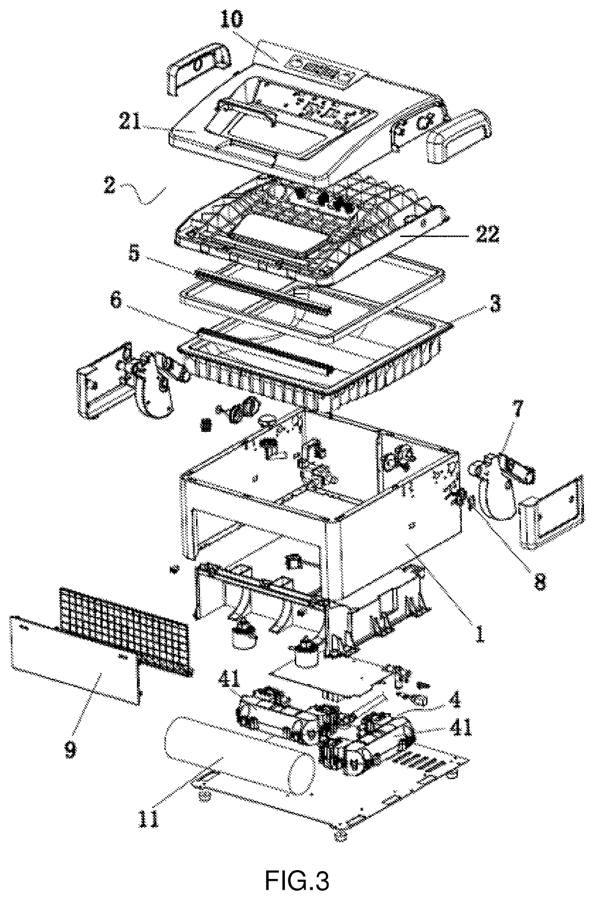
[0029]As shown in FIG. 1, FIG. 2 and FIG. 3, a cavity-type vacuum sealing machine comprises a machine body 1 and a cover 2 which covers the machine body. The cover 2 comprises an upper cover 21 and a lower cover 22, which fit together; and a control panel 10 is arranged on the upper cover 21. The machine body 1 is internally provided with a tray 3; an airtight cavity for holding the packaging bags is formed between the tray 3 and the cover 1; and the cavity is internally provided with a hot-pressing bar 5 and a heating and sealing component 6 for sealing the packaging bags. The bottom side of the tray 3 is an oblique plane; the mouth of the packaging bag is located at the top of the oblique plane. While being sealed, the packaging bag is arranged on a slant on the tray 3; if the packaging bag contains liquid, the liquid flows from the bottom side ...


PUM


Abstract

The utility model discloses a cavity-type vacuum sealing machine, comprising a machine body and a cover which covers the machine body. The machine body is internally provided with a tray; an airtight cavity for holding packaging bags is formed between the tray and the cover; the cavity is internally provided with a hot-pressing bar and a heating and sealing component for sealing the packaging bags; the machine body is internally provided with a vacuum pump set for vacuumization; and the suction ports of the vacuum pump set communicate with the airtight cavity for holding the packaging bags via tubes. The cavity-type vacuum machine disclosed by the utility model has the advantages of smaller volume and small occupied space.

Description

BACKGROUND OF THE INVENTION[0001]The utility model relates to the field of the vacuum sealing machine, in particular to a cavity-type vacuum sealing machine with small volume and low cost.[0002]The vacuum sealing machine finishes the sealing procedure by putting food into a packaging bag and pumping air out of the packaging bag to achieve the predetermined vacuum degree. The vacuum sealing machine can have the following functions of vacuumizing and sealing the bag or directly sealing the mouth of the bag. The prior vacuum sealing machine is generally divided into two types; one is a direct-pump type incapable of packaging products containing high liquid and the other is a cavity type capable of packaging products containing high liquid or pure liquid products. However, the prior cavity-type vacuum sealing machine is only used in the large production occasions such as factories; and the vacuum sealing machine utilizes a large vacuum pump, has the disadvantages of complex structure, h...

Claims


Application Information

Patent Timeline
Patent Type & Authority Patents(United States)
IPC IPC(8): F04B1/00B65B51/10B65B51/14B65B31/04B65B31/02
CPCB65B31/024B65B51/10B65B51/146
Inventor HU, ZHIHEZHENG, XINZHAI
Owner BIGLAND ELECTRIC APPLIANCE
Why Eureka
Try Eureka