Needle threader for sewing machine

a technology for sewing machines and needles, applied in sewing machines, needle bars, textiles and paper, etc., can solve problems such as reducing visibility, and achieve the effects of saving time, smooth vertical movement, and efficient operation

Active Publication Date: 2009-07-23
BROTHER KOGYO KK
View PDF6 Cites 8 Cited by
  • Summary
  • Abstract
  • Description
  • Claims
  • Application Information

AI Technical Summary

Benefits of technology

[0021]The locking mechanism includes an engagement protrusion engageable with the slider and a cam plate having a grooved cam which extends in an up-and-down direction and which the engagement protrusion engages thereby to be guided. In this case, the grooved cam has an upper end provided with a first locking portion which locks the engagement protrusion thereby to stop the slider at the first position, an intermediate part provided with a second locking portion which locks the engagement protrusion thereby to stop the slider at the second position, and a lower end provided with a threading position which lowers the slider to a third position corresponding to the threading operation position. The engagement protrusion provided on the slider is engaged with the grooved cam to be guided, whereupon the slider can smoothly be moved vertically. Furthermore, since the grooved cam is provided with the first and second locking portions, the slider can reliably be retained in the stopped state at the first and second positions.
[0022]The grooved cam of the cam plate has a first path which guides the engagement protrusion so that the engagement protrusion is moved from the first locking portion to the second locking portion and further moved down to the threading position and a second path which guides the engagement protrusion so that the engagement protrusion is returned from the threading position to the first locking portion without passing the second locking portion. When the slider is moved downward from the first position to the second position and further to the third position, the engagement protrusion is moved along the first path of the cam groove. When the slider is moved upward from the third position to the first position, the engagement protrusion is moved along the second path differing from the first path. Consequently, since the slid

Problems solved by technology

Accordingly, the threading hook and the thread guide members block the user's view when the user views

Method used


Image

  • Needle threader for sewing machine
  • Needle threader for sewing machine
  • Needle threader for sewing machine

Examples


first embodiment

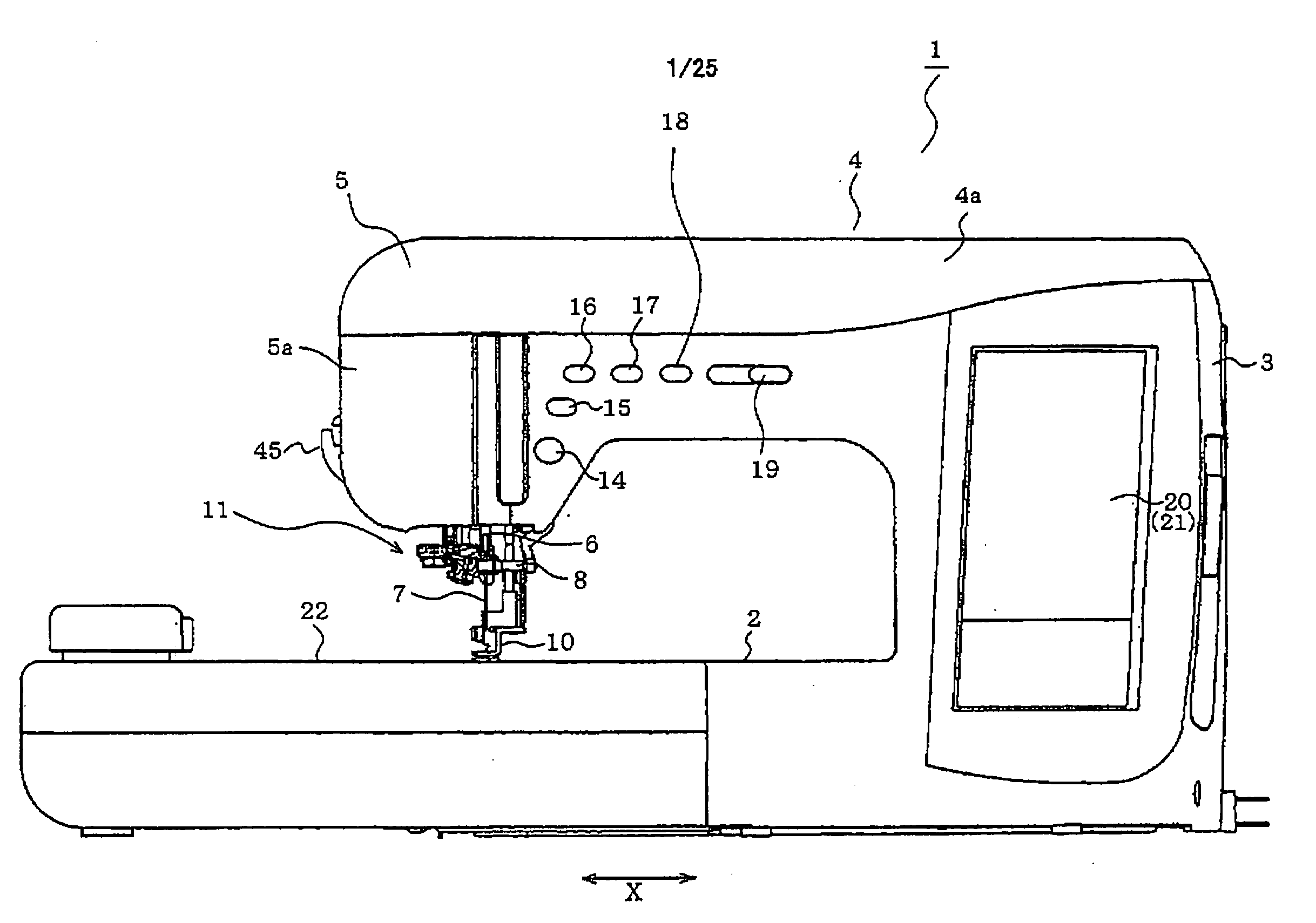
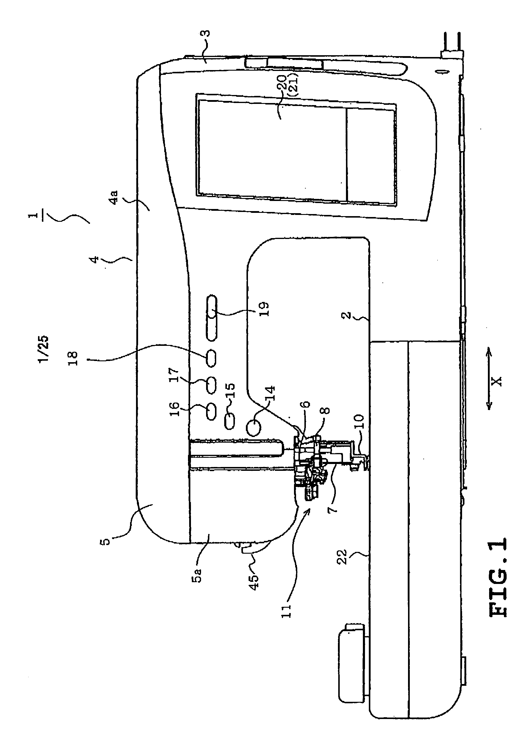
[0048]A first embodiment will now be described with reference to FIGS. 1 to 8. Referring to FIG. 1, a household electronic sewing machine to which a needle threader of the embodiment is applied is shown. A sewing machine body 1 includes a sewing machine bed 2 extending in a horizontal direction (the X direction), a pillar 3 extending upward from a right end of the bed 2, and an arm 4 extending leftward from an upper end of the pillar 3, all of which are formed integrally with the body 1. The arm 4 has a distal end serving as a-head 5. Furthermore, a cover 4a is mounted on an upper part of the arm 4 so as to be closed and opened. A thread spool accommodating space is defined in a space inside the cover 4a in the arm 4 although not shown. A needle thread spool serving as a needle thread supply is adapted to be detachably set into the thread spool accommodating space. The needle thread spool can be attached and detached (replaced) when the cover 4a is opened.

[0049]A needlebar 6 is moun...

second embodiment

[0084]In the second embodiment, the control device 62 sets either threading mode in a procedure as shown in the flowchart of FIG. 9. Furthermore, the threading mode can be selected when the user operates the touch panel 21. Accordingly, the control device 62 and the touch panel 62 serve as a mode setting unit. Firstly, at step S1, it is determined whether an embroidering operation is executed. In this case, the determination can be made by selecting an embroidery pattern or an ordinary pattern on the touch panel 21. When the embroidery pattern has been selected, it is of course determined that the embroidering operation be executed. Alternatively, execution of the embroidering operation may be determined while the embroidery machine 22 is attached to the sewing machine bed 2. When the embroidering operation has been determined to be executed (YES at step S1), the second threading mode is set at step S2.

[0085]On the other hand, when it is not determined that the embroidering operatio...

fourth embodiment

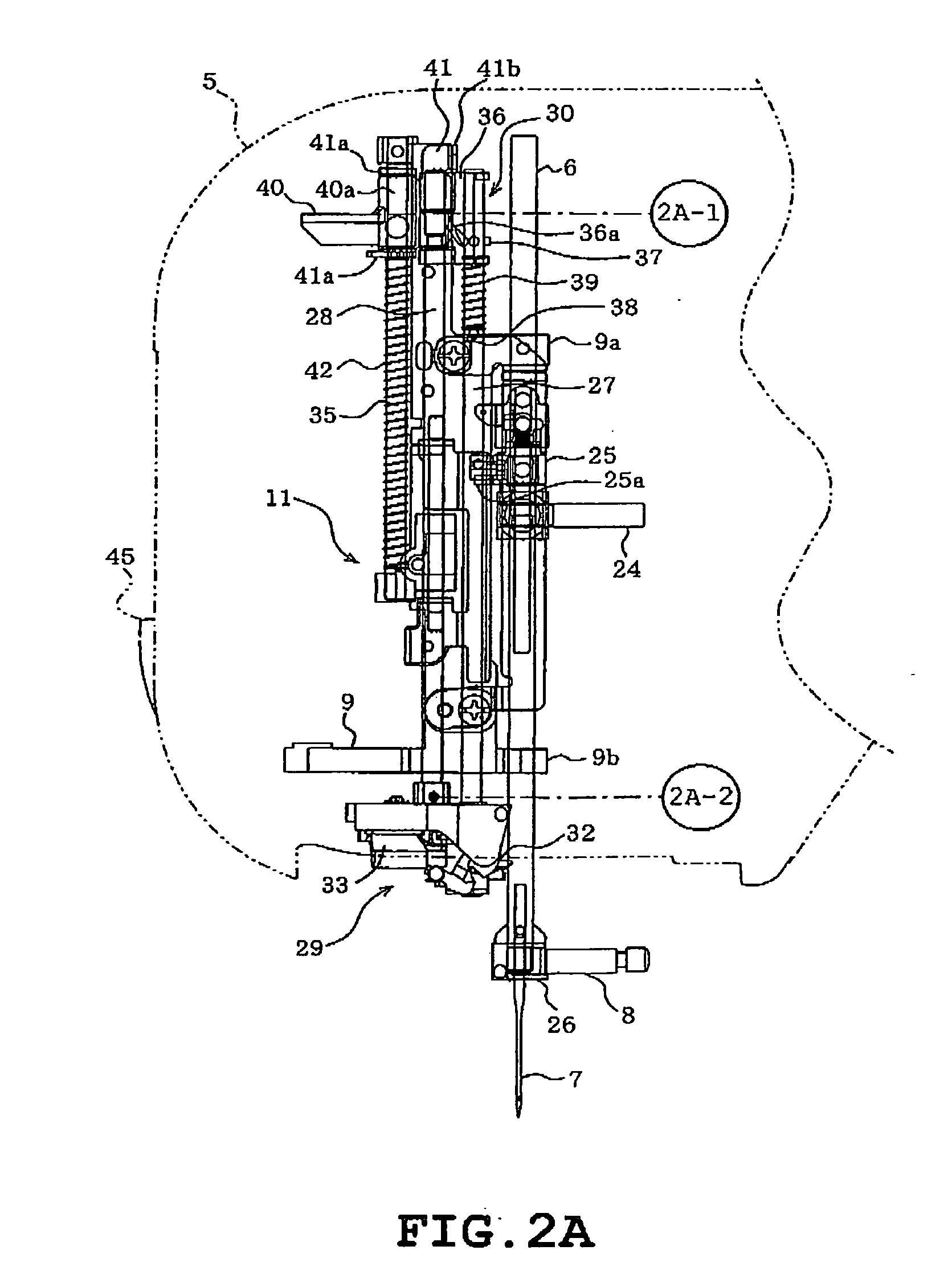
[0122]According to the foregoing fourth embodiment, the needle threader 11 is provided in the sewing machine for threading the needle 7 or causing the needle thread T to pass through the eye 7a of the needle 7. The threading mechanism 29 (including the threading hook 31 and the thread guide member 32) can be located at the retreat position where the threading mechanism 29 is moved upward to the inside of the face plate 5a of the head 5. Accordingly, the threading mechanism 29 and the like can be prevented from blocking the user's view when he or she views the needle base portion including the needle 7 and the periphery thereof, whereupon the user's visibility can be improved.

[0123]Furthermore, the needle threader is provided with the vertical moving mechanism 34 (automatic position changeover unit) having the rack and pinion mechanism 52 with the threading pulse motor 49 serving as the drive source as well as the manual operating mechanism 81 having the operation knob 89, the slider...


PUM


Abstract

A needle threader for a sewing machine includes a threading mechanism including a threading hook mounted on a lower end of a threading shaft and a thread guide member. The threading hook and the thread guide member are movable among a thread guide preparation position where the threading hook and the thread guide member are located near a height position of a needle clamp, a threading operation position where a threading operation is carried out with the threading hook being level with an eye of a needle, and a retreat position which is located above the thread guide preparation position and to which the threading hook and the thread guide member are retreated. A vertical moving mechanism moves the threading shaft vertically so that the threading mechanism is moved between the thread guide preparation position and the threading operation position.

Description

CROSS-REFERENCE TO RELATED APPLICATIONS[0001]This application is based upon and claims the benefit of priority from the prior Japanese Patent Application Nos. 2008-009315 and 2008-009316 both filed on Jan. 18, 2008, the entire contents of which are incorporated herein by reference.BACKGROUND[0002]1. Technical Field[0003]The present disclosure relates to a needle threader for a sewing machine, which is provided in a head of a sewing machine body for threading a sewing machine needle mounted on a lower end of a needlebar by causing a needle thread from a needle thread supply to pass through an eye of the needle.[0004]2. Description of the Related Art[0005]Needle threaders of the above-described type have conventionally been known. For example, Japanese patent application publication JP-A-2002-200387 discloses a needle threader provided with a threading shaft that is located near or on the left of a needlebar so as to be vertically movable and pivotable. The threading shaft has a lower...

Claims


Application Information

Patent Timeline
IPC IPC(8): D05B87/02
CPCD05B87/02
Inventor FUJIHARA, SHINYA
Owner BROTHER KOGYO KK
Why Eureka
Try Eureka