Multiple oven

Inactive Publication Date: 2009-07-23
BSH BOSCH & SIEMENS HAUSGERAETE GMBH
View PDF13 Cites 11 Cited by
  • Summary
  • Abstract
  • Description
  • Claims
  • Application Information

AI Technical Summary

Benefits of technology

[0011]It is advantageous, for effective separation of the vapor from a fresh air area, for the vapor suction duct to cover the associated vapor outlet. Advantageously the vapor suction duct also encloses the associated vapor outlet

Problems solved by technology

The fact that the fans are offset to the side means that the vapor outlets must also be offset accordingly, since otherwise the distance between at least one of the fans and the assigned vapor outlet is too large for a effective e

Method used


Image

  • Multiple oven
  • Multiple oven

Examples


Example

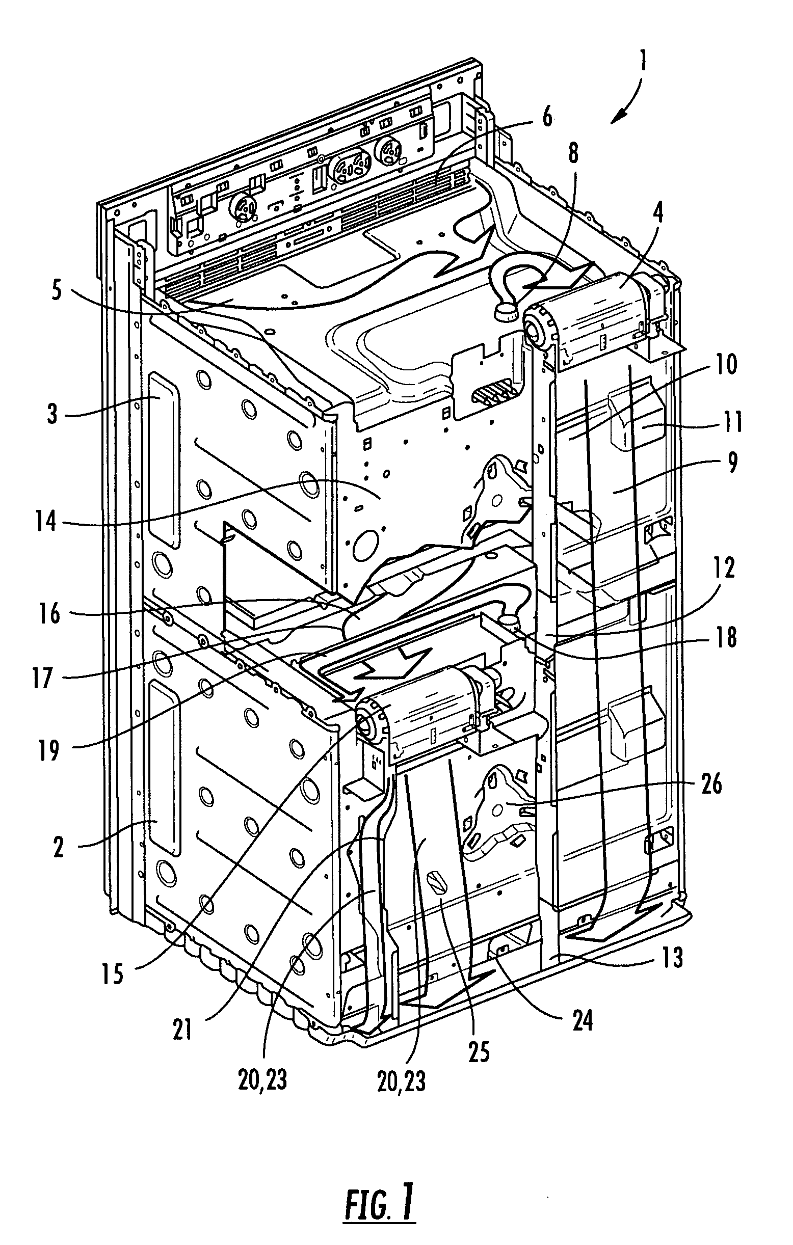
[0014]A double oven 1, which is shown without the built-in housing, features a lower oven 2 and an upper oven 3 arranged above it. At a rear edge area of the upper oven 3 an upper fan 4 in the form of a crossflow fan is arranged so as to enable it suck in fresh air 5, as indicated by the arrow shape, through a front ventilation grid 6 via an upper side [7] of the upper oven 3. Incorporated into the upper side [7] is an upper vapor outlet 8 through which vapor can be extracted from the oven space (not shown). Vapor exiting from the vapor outlet 8 is likewise sucked in by the upper fan 4, as indicated by the associated arrow. So that the vapor is completely sucked in where possible, the vapor outlet 8 is provided in the lower right-hand area of the upper side [7] of the upper oven 3, and the upper fan 4 is located for this purpose at a short distance from the edge area lying immediately behind it. From the upper fan 4 mixed air containing vapor is taken out through a first exhaust duc...


PUM


Abstract

A multiple oven, especially a double oven, with at least one lower oven and an upper oven arranged above it, features an upper fan for sucking in air over a surface of the upper oven, which features an upper vapor outlet, and also a lower fan for sucking in air over a surface of the lower oven, which features a lower vapor outlet. The multiple oven further features at least one vapor suction duct which is present for directing vapor exiting from the vapor outlet to one of the associated fans.

Description

BACKGROUND OF THE INVENTION[0001]Double ovens, comprising ovens or oven cavities arranged one above the other are known, in which each of the ovens features a fan for sucking in air over its upper side, with a vapor outlet being inserted into the upper side in each case. Typically fresh air is sucked in from the front over the upper side to a fan mounted at the rear, and then from there as exhaust air containing vapor along the rear of the double oven in a floor area and onwards through the floor area to a front-side oven exhaust air opening.[0002]Since the fans occupy a comparatively large volume, they are arranged (when viewed from the rear) offset to the side, so that the lower fan does not reduce the flow cross section of an exhaust air duct of an upper fan too much. The then likewise offset exhaust air ducts of upper fan and lower fan merge back into each other in the floor area. The fact that the fans are offset to the side means that the vapor outlets must also be offset acco...

Claims


Application Information

Patent Timeline
IPC IPC(8): F24C15/00
CPCF24C15/2007F24C15/006
Inventor HASSLBERGER, ROBERTHOFMANN, JOHANNMEISINGER, CHRISTIANROSENBAUER, JORGSCHUCHHARDT, JURGENSCHUCHHARDT, NESRINTHEINE, MARKUS
Owner BSH BOSCH & SIEMENS HAUSGERAETE GMBH
Why Eureka
Try Eureka