Connecting joint of prefabricated steel pipe restraining reinforced concrete pier and bearing platform

A technology of reinforced concrete and connecting nodes, applied in bridges, bridge construction, bridge parts, etc., can solve the problems of insufficient bearing capacity and rigidity, unfavorable structural safety, damage and collapse of bridge piers, etc., to achieve high bearing capacity, simplify the formwork process, The effect of improving construction quality

Active Publication Date: 2018-08-03
CHONGQING UNIV
View PDF7 Cites 9 Cited by
  • Summary
  • Abstract
  • Description
  • Claims
  • Application Information

AI Technical Summary

Problems solved by technology

However, in the prior art, the joints between prefabricated steel pipe-constrained reinforced concrete piers and caps often have a risk of damage due to insufficient bearing capacity and stiffness.
Under the action of a relatively destructive strong earthquake, if the joint stiffness between the prefabricated pier and the cap is insufficient, the top and bottom of the pier will have a large displacement, which will form eccentric compression on the pier, and then increase under the gravity of the bridge superstructure. Eccentricity, which may lead to damage and collapse of pier in severe cases
Insufficient bearing capacity will cause the node to be damaged and form a plastic hinge, which is extremely unfavorable to structural safety.

Method used


Image

  • Connecting joint of prefabricated steel pipe restraining reinforced concrete pier and bearing platform
  • Connecting joint of prefabricated steel pipe restraining reinforced concrete pier and bearing platform
  • Connecting joint of prefabricated steel pipe restraining reinforced concrete pier and bearing platform

Examples


Embodiment 1

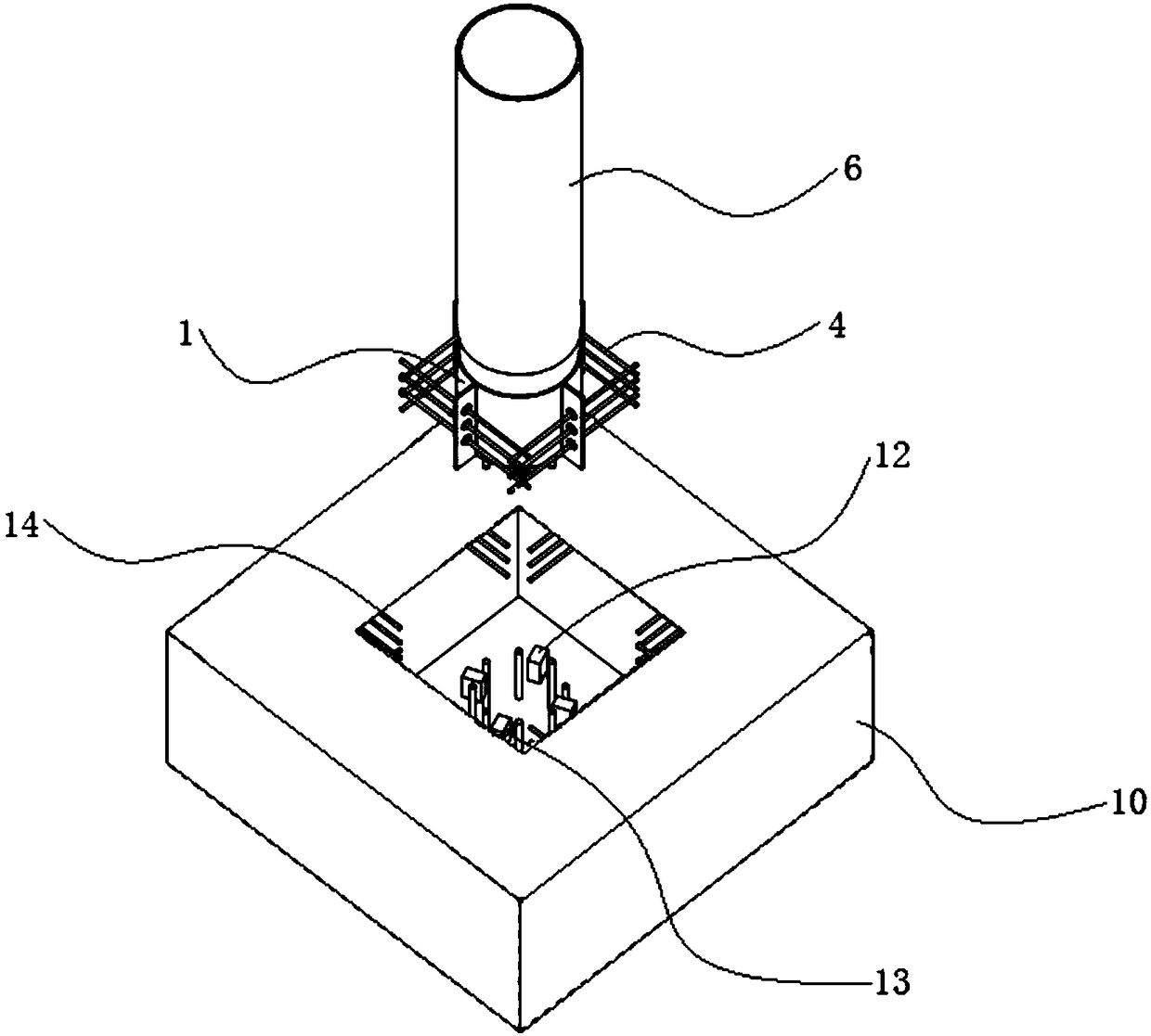
[0039] see figure 1 , this embodiment discloses a connection node between a prefabricated steel pipe-constrained reinforced concrete bridge pier and a cap, including a prefabricated bridge pier and a cap 10 .

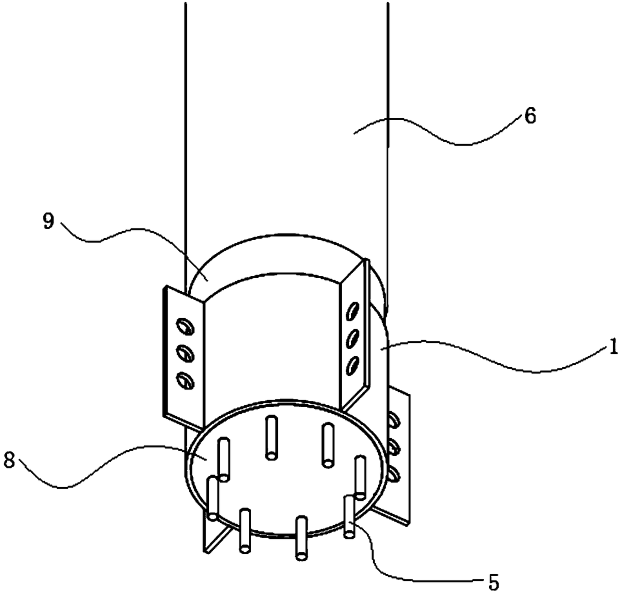
[0040] The prefabricated bridge pier includes steel pipe nodes, upper steel pipes 6 and concrete 8 .

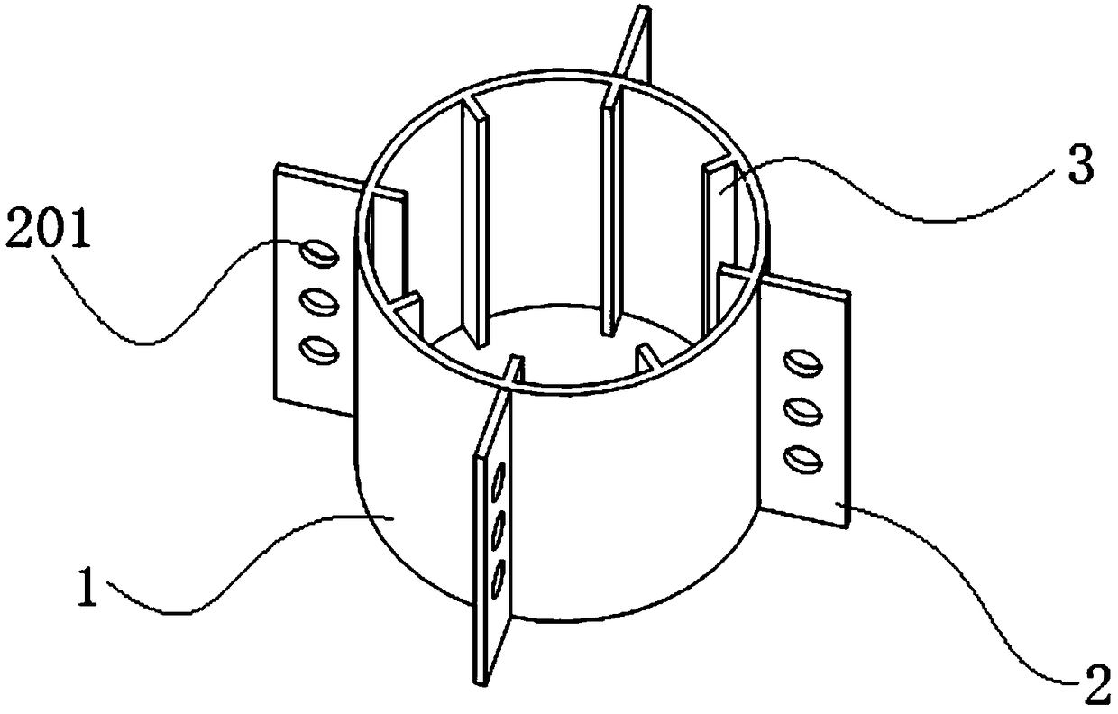
[0041] see figure 2 , the steel pipe node includes a lower steel pipe 1 , a perforated steel plate 2 and a connecting steel plate 3 .

[0042] The lower steel pipe 1 is a hollow cylinder with open upper and lower ends. On the peripheral outer wall of the lower steel pipe 1, four steel plates 2 with vertical holes are evenly arranged along the circumferential direction. Three holes 201 are arranged vertically on the surface of the perforated steel plate 2 . Corresponding holes 201 on two adjacent perforated steel plates 2 are arranged in dislocation. The perforated steel bars 4 are perforated in the holes 201 . The 12 perforated steel bars 4 form 4 rows, with 3 ba...

Embodiment 2

[0047] In order to improve the mechanical properties at the joint between the prefabricated bridge pier and the cap, this embodiment discloses a connection node between the prefabricated steel pipe-constrained reinforced concrete pier and the cap, including the prefabricated bridge pier and the cap 10 .

[0048] The prefabricated bridge pier includes steel pipe nodes, upper steel pipes 6 and concrete 8 .

[0049] The steel pipe node includes a lower steel pipe 1 , a perforated steel plate 2 and a connecting steel plate 3 .

[0050] The lower steel pipe 1 is a hollow cylinder with open upper and lower ends. On the peripheral outer wall of the lower steel pipe 1, four steel plates 2 with vertical holes are evenly arranged along the circumferential direction. Five holes 201 are arranged vertically on the surface of the perforated steel plate 2 . Corresponding holes 201 on two adjacent perforated steel plates 2 are arranged in dislocation. The perforated steel bars 4 are perfor...

Embodiment 3

[0056] This embodiment discloses a construction method for the connection node between the prefabricated steel pipe restrained reinforced concrete bridge pier and the bearing platform described in Embodiment 2, including the following steps:

[0057] 1) Make steel pipe nodes. The perforated steel plate 2 is welded on the outer wall of the lower steel pipe 1 . The steel plate 3 is welded and connected to the inner wall of the lower steel pipe 1 .

[0058] 2) Arranging the longitudinal reinforcement bars 5, and welding the longitudinal reinforcement bars 5 and the connecting steel plates 3 in one-to-one correspondence.

[0059] 3) Pouring pier concrete 8. Formwork is supported at the disconnected part in the middle of the lower steel pipe 1 and the upper steel pipe 6 and the top surface of the upper steel pipe 6 . After the template is fixed, concrete 8 is poured in the vertical cavity formed by the lower steel pipe 1, the upper steel pipe 6 and the template. Curing concrete...


PUM


Abstract

The invention provides a connecting joint of a prefabricated steel pipe restraining reinforced concrete pier and a bearing platform and a construction method thereof. The connecting joint connects a prefabricated bridge pier and a bearing platform. The prefabricated bridge pier includes a steel pipe joint, an upper steel pipe and concrete. The steel pipe joint includes a lower steel pipe, a perforated steel plate and a connecting steel plate. The upper steel pipe is arranged above the lower steel pipe. The construction method of the connecting joint includes manufacturing a steel pipe joint, arranging longitudinal steel bars, pouring bridge pier concrete, hoisting a prefabricated pier and pouring filling concrete and the like. The connecting joint simplifies the formwork process. The construction speed is fast. The construction quality is improved. The construction environment is improved. The labor cost and the construction cost are saved. The bearing capacity of the connecting jointof the prefabricated pier and the bearing platform is improved on the basis of ensuring that the outer-wrapped steel pipe does not bear vertical load and greater lateral binding force on the core concrete is provided.

Description

technical field [0001] The invention relates to the technical field of bridge components, in particular to a connection node between a bridge pier and a cap. Background technique [0002] The steel pipe confined concrete structure has the advantages of high bearing capacity, superior earthquake resistance and fire resistance, and can make full use of high-strength steel and concrete compressive strength. When the steel pipe restrains the reinforced concrete column and the outsourcing steel pipe is circular, the steel pipe restrains the core concrete uniformly, the tensile strength of the steel pipe can be fully utilized, and the economic benefit is good. [0003] With the sharp increase in traffic volume and the increase in the service life of basic transportation facilities, steel pipe-confined concrete piers have been widely used in building structures. However, in the prior art, the joints between the prefabricated steel pipe-constrained reinforced concrete piers and the...

Claims


Application Information

Patent Timeline
Patent Type & Authority Applications(China)
IPC IPC(8): E01D19/02E01D21/00
CPCE01D19/02E01D21/00
Inventor 周绪红狄谨李浩徐梁晋涂熙
Owner CHONGQING UNIV
Why Eureka
Try Eureka