Clamp apparatus

a technology of clamping apparatus and workpiece, which is applied in the direction of positioning apparatus, metal-working machine components, manufacturing tools, etc., can solve the problems of workpiece being dropped from the clamping apparatus, workpiece being subjected to shifting, and inability to position at the desired position, etc., to achieve the effect of simple structure and reliable retention of workpieces

Active Publication Date: 2009-07-23
SMC CORP
View PDF14 Cites 11 Cited by
  • Summary
  • Abstract
  • Description
  • Claims
  • Application Information

AI Technical Summary

Benefits of technology

[0010]A general object of the present invention is to provide a clamp apparatus, which can reliably retain workpieces by means of a simple structure, and further in which the retaining force thereof can suitably be maintained.

Problems solved by technology

However, in a state in which the workpiece is clamped, in the event that the supply of air is halted for some reason, the clamped state of the clamp arm with respect to the workpiece becomes released and the held state of the workpiece cannot be maintained, thus resulting in the workpiece being dropped from the clamp apparatus or the like.
As a result, the clamping force applied to the workpiece tends to be small.
In addition, in the case that a variance occurs in the thickness of the workpiece, the clamped state becomes unstable, and there is a fear that the workpiece may be subjected to shifting and cannot be positioned at a desired position.
Further, because the locking cylinder, including the locking spring and the locking piston, must be assembled in the clamp apparatus, the structure of the clamp apparatus is complicated and made larger in scale.

Method used


Image

  • Clamp apparatus
  • Clamp apparatus
  • Clamp apparatus

Examples


first embodiment

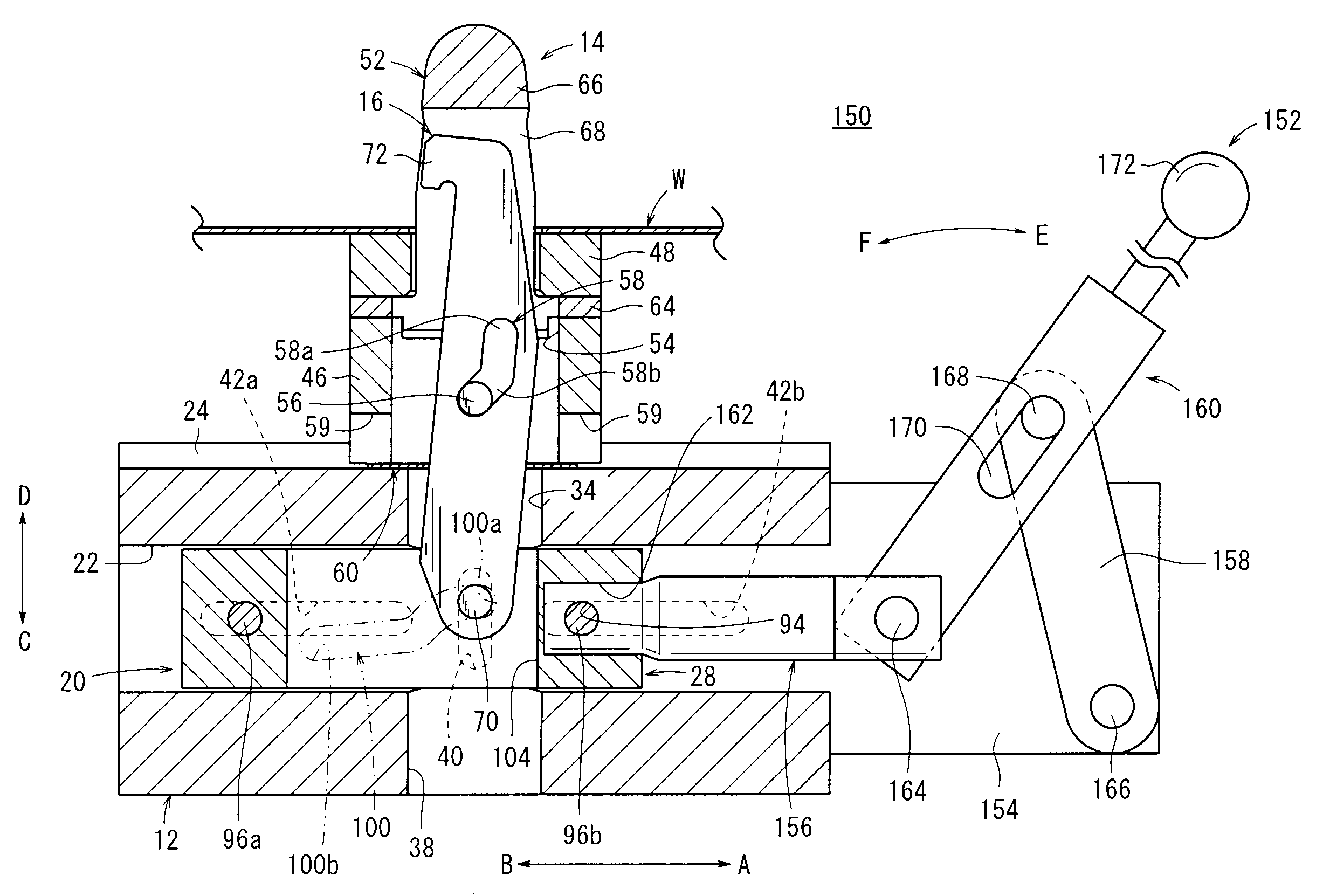
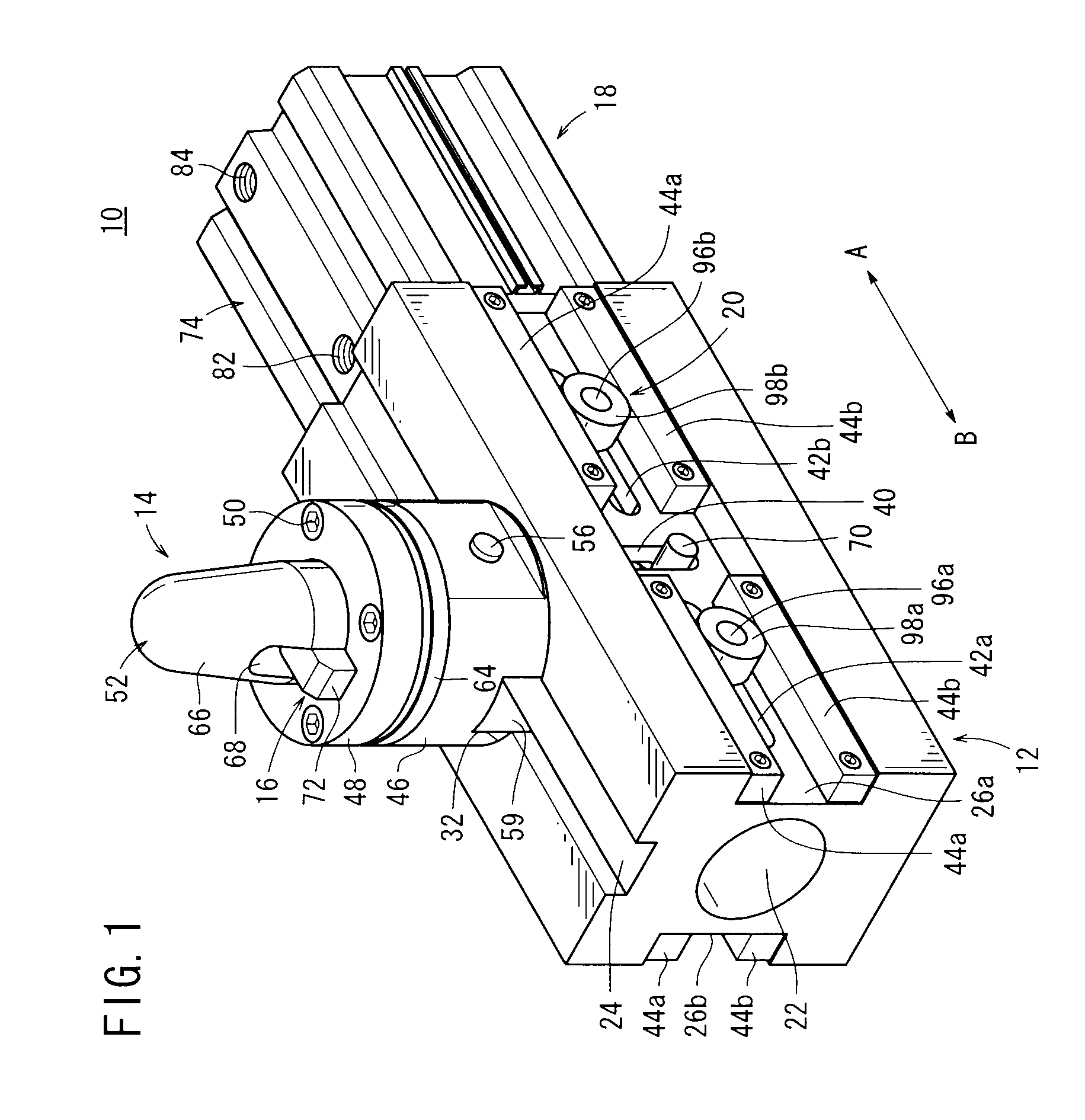
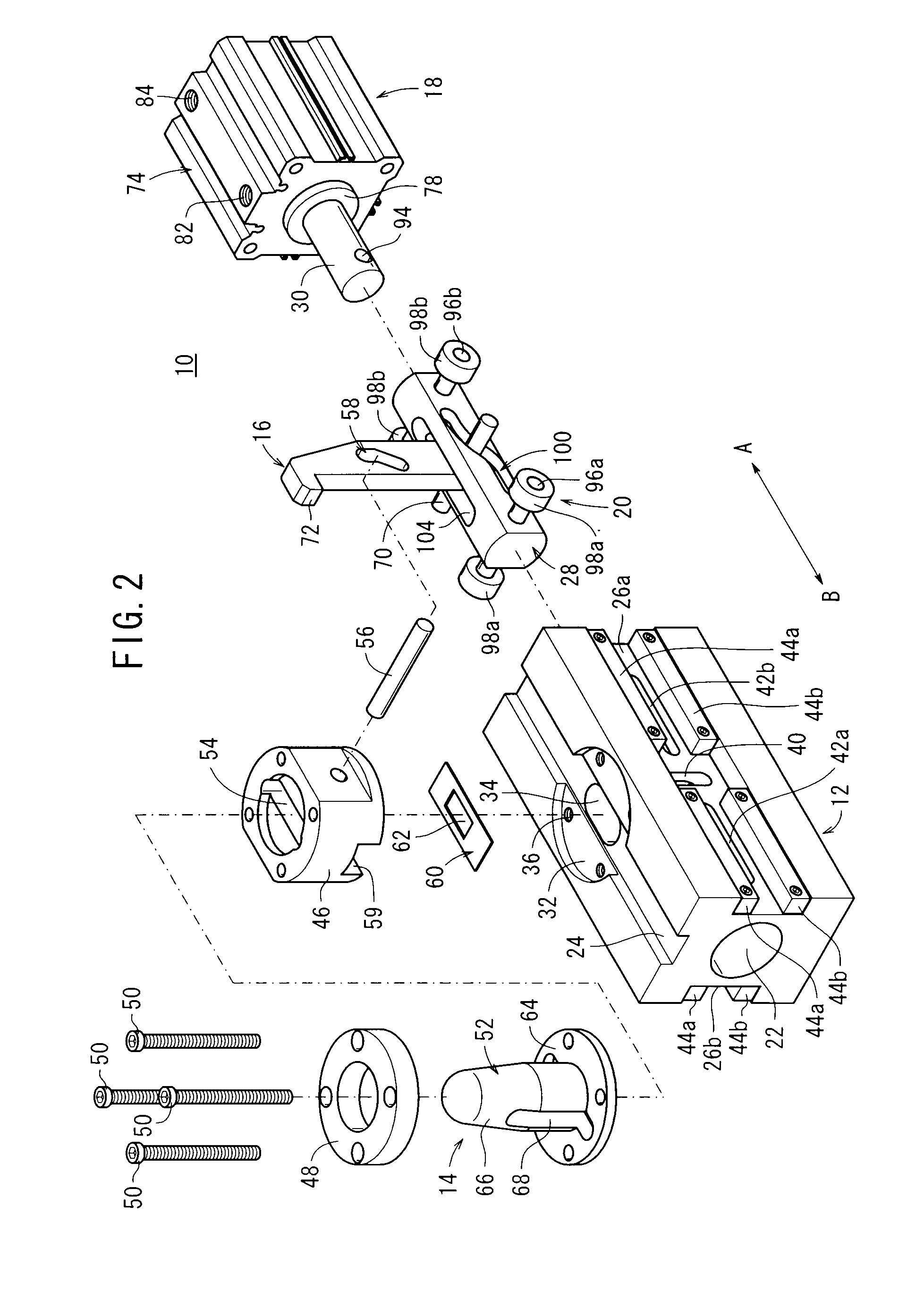
[0032]In FIG. 1, reference numeral 10 indicates a clamp apparatus according to the present invention.

[0033]The clamp apparatus 10, as shown in FIGS. 1 to 7, includes a hollow body 12, a clamp unit 14 disposed on an upper portion of the body 12, which is capable of retaining a workpiece W (see FIG. 4), a cylinder (driving section) 18 connected to an end of the body 12, which is capable of rotating a clamp arm 16 of the clamp unit 14 under the supply of a pressure fluid, and a drive force transmission mechanism 20 disposed in the interior of the body 12, which is capable of transmitting a drive force from the cylinder 18 to the clamp unit 14. The workpiece W retained by the clamp apparatus 10, for example, comprises a panel formed from a plate-like material, which is used in an automobile. The clamp apparatus 10 is used in a production line in which such an automotive panel is retained and is welded.

[0034]The body 12 is formed with a substantially rectangular shape in cross section, a...


PUM


Abstract

A clamp apparatus includes a clamp unit capable of retaining a workpiece, a cylinder driven under the supply of a pressure fluid, and a drive force transmission mechanism, which is capable of transmitting a drive force from the cylinder to the clamp unit. The drive force transmission mechanism includes a guide body disposed displaceably inside of a body, two pairs of rollers retained rotatably on both side surfaces of the guide body, and a spindle inserted through a second link groove of the guide body that rotatably supports a clamp arm. The clamp arm is rotatably operated and is capable of clamping the workpiece under a displacement action of the guide body.

Description

BACKGROUND OF THE INVENTION[0001]1. Field of the Invention[0002]The present invention relates to a clamp apparatus, which is capable of retaining a workpiece by a clamp arm through a drive force of a driving section.[0003]2. Description of the Related Art[0004]Heretofore, for example, when structural components of an automobile or the like are welded, a clamp apparatus is used for clamping the structural components.[0005]In this type of clamp apparatus, for example, a piston is displaced under the supply of air, thereby causing rotary movement of a clamp arm through the piston for clamping the workpiece. However, in a state in which the workpiece is clamped, in the event that the supply of air is halted for some reason, the clamped state of the clamp arm with respect to the workpiece becomes released and the held state of the workpiece cannot be maintained, thus resulting in the workpiece being dropped from the clamp apparatus or the like.[0006]In response to the aforementioned prob...

Claims


Application Information

Patent Timeline
Patent Type & Authority Applications(United States)
IPC IPC(8): B25B5/06B25B5/04
CPCB25B5/087
Inventor HIROMATSU, YOSHINORI
Owner SMC CORP
Why Eureka
Try Eureka