LED illuminantor and heat-dissipating method thereof

Inactive Publication Date: 2009-07-23
FOXSEMICON INTEGRATED TECH INC
View PDF7 Cites 24 Cited by
  • Summary
  • Abstract
  • Description
  • Claims
  • Application Information

AI Technical Summary

Problems solved by technology

LEDs generally emit visible light at specific wavelengths and generate a significant amount of heat.
If the generated heat cannot be timely dissipated, the LEDs may overheat, and thus the performance and lifespan maybe significantly reduced.
However, during the working process of the heat-dissipati

Method used


Image

  • LED illuminantor and heat-dissipating method thereof
  • LED illuminantor and heat-dissipating method thereof
  • LED illuminantor and heat-dissipating method thereof

Examples


Example

[0013]An embodiment will now be described in detail below and with reference to the drawings.

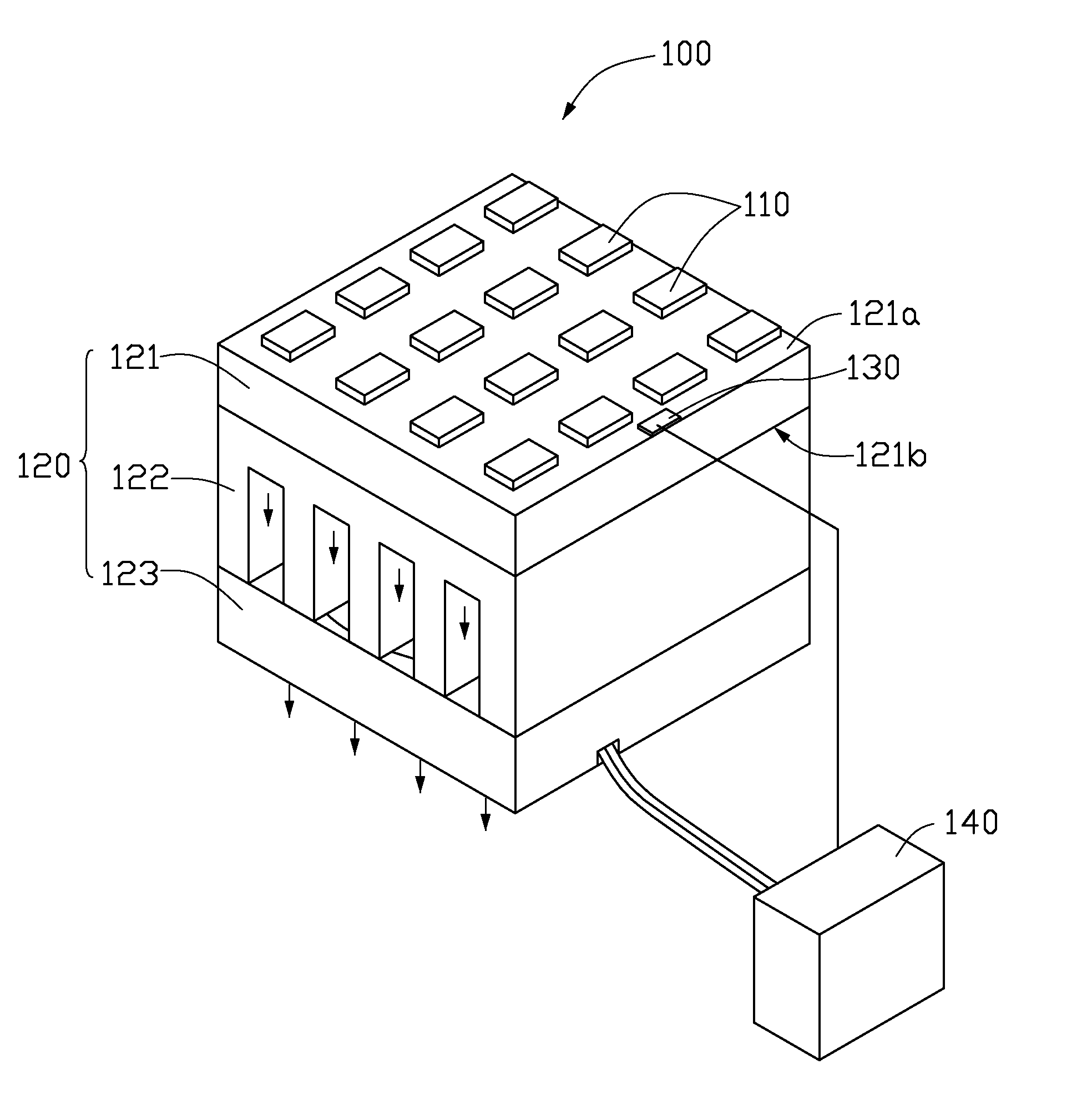
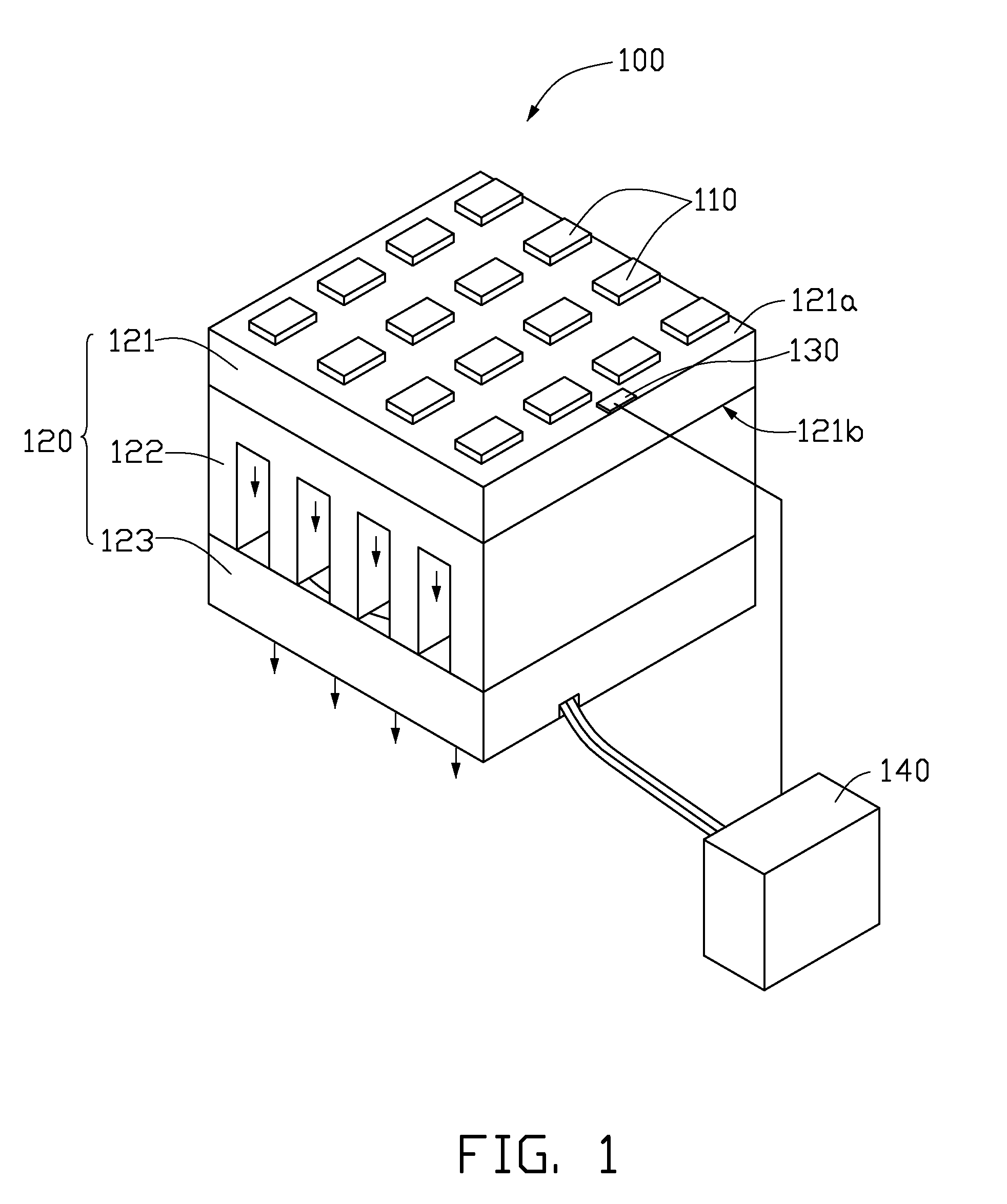
[0014]Referring to FIG. 1, a LED illuminator 100 according to an exemplary embodiment is illustrated. The LED illuminator 100 includes at least a LED 110, a heat-dissipating apparatus 120, a temperature sensor 130, and a controller 140.

[0015]The heat-dissipating apparatus 120 includes a heat-dissipating base 121, a heat sink 122 and a fan 123. The heat-dissipating base 121 includes a first surface 121a and a second surface 121b on an opposite side of the first surface 121a. The LED 110 is defined on the first surface 121a of the heat-dissipating base 121. The heat sink 122 is thermally connected to the second surface 121b of the heat-dissipating base 121. The fan 123 is coupled with the heat sink 122, and cooperates with the heat sink 122 to dissipate heat generated from the LED 110.

[0016]The temperature sensor 130 can be thermally connected to the heat-dissipating base 121 or the heat sink ...


PUM


Abstract

A heat-dissipating method of a light emitting diode illuminator includes the following steps. First, the light emitting diode illuminator is provided and includes a light emitting diode, a fan apparatus, a temperature sensor and a controller. The controller is electrically connected with the fan and the temperature sensor. Second, a predetermined working temperature of the light emitting diode is defined in the controller. Third, a working temperature of the light emitting diode is sensed using the temperature sensor, and a signal of the working temperature is transmitted to the controller. Fourth, the working temperature sensed by the temperature sensor is compared with the predetermined working temperature in the controller, and the fan is adjusted by the controller to work at a suitable speed.

Description

BACKGROUND[0001]1. Field of the Invention[0002]The present invention relates to illuminators and, particularly, to a light emitting diode (LED) illuminator and a heat-dissipating method thereof.[0003]2. Description of related art[0004]With the continuing development of scientific technology, light emitting diodes (LEDs) have been widely used in the field of illumination due to its high brightness, long lifespan, wide color gamut and so on. LEDs generally emit visible light at specific wavelengths and generate a significant amount of heat. Generally, approximately 80-90% of the electric energy consumed by the LEDs is converted to heat, with the remainder of the electric energy converted to light. If the generated heat cannot be timely dissipated, the LEDs may overheat, and thus the performance and lifespan maybe significantly reduced.[0005]Therefore, heat-dissipating apparatuses are applied in the illuminators to timely dissipate heat generated by the LEDs. The heat-dissipating appar...

Claims


Application Information

Patent Timeline
IPC IPC(8): H01K1/58F21V29/00F21V21/00
CPCF21K9/00F21S48/325F21V29/763F21Y2101/02F21V29/02F21Y2115/10F21V29/503F21V29/67
Inventor LAI, CHIH-MING
Owner FOXSEMICON INTEGRATED TECH INC
Why Eureka
Try Eureka