
Low-backlight image visibility enhancement method and system

Inactive Publication Date: 2009-07-23
NAT TAIWAN UNIV
View PDF9 Cites 21 Cited by
  • Summary
  • Abstract
  • Description
  • Claims
  • Application Information

AI Technical Summary

Benefits of technology

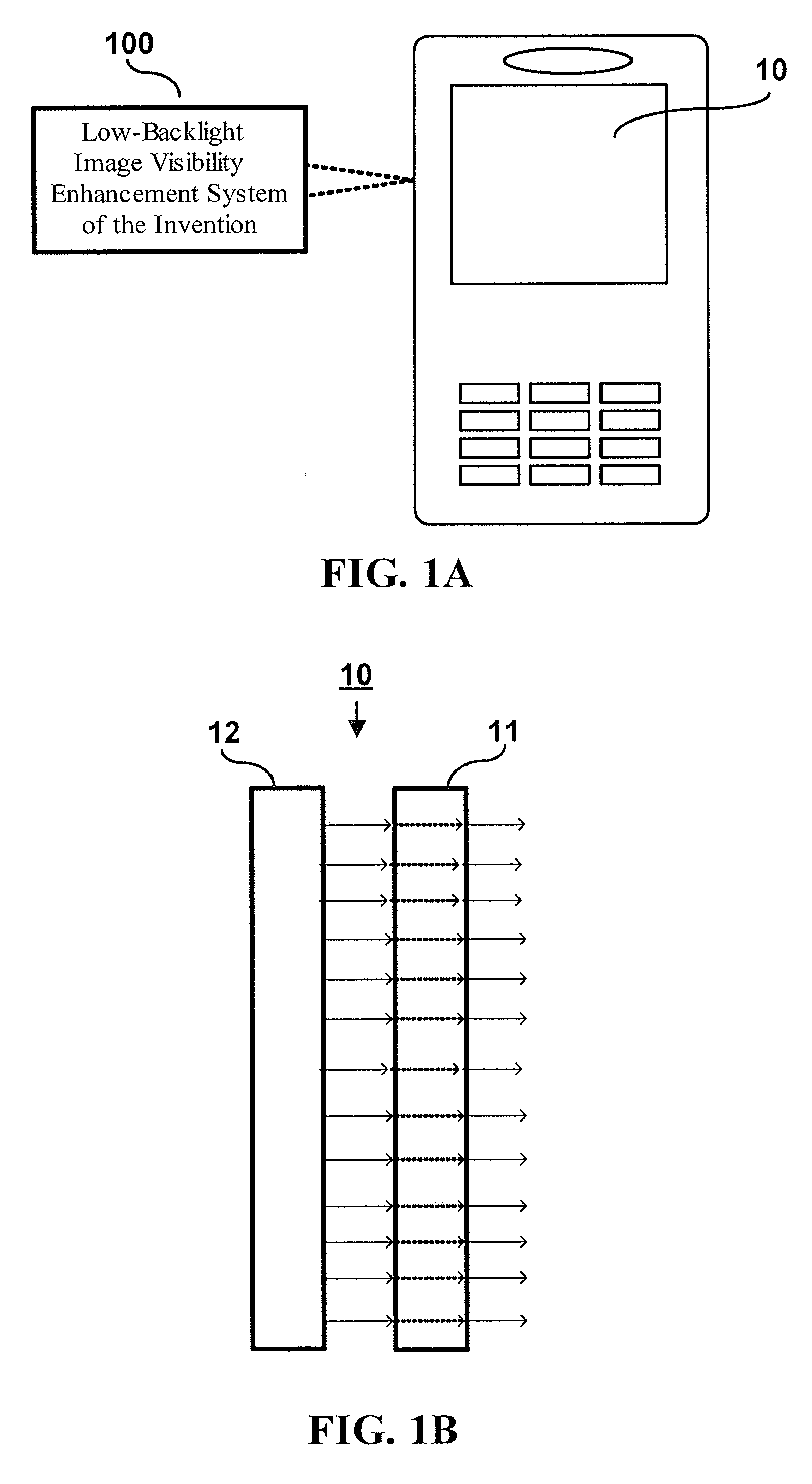
[0008]It is therefore an objective of this invention to provide a low-backlight image visibility enhancement method and system for use on TFT-LCD that allows TFT-LCD to use a lowered level of backlight while nonetheless allowing the displayed image to have a good level of visibility to the user.
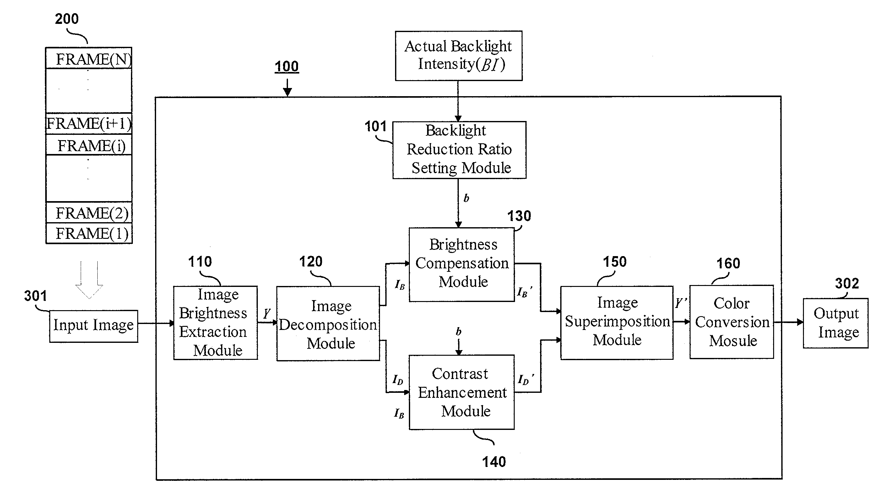
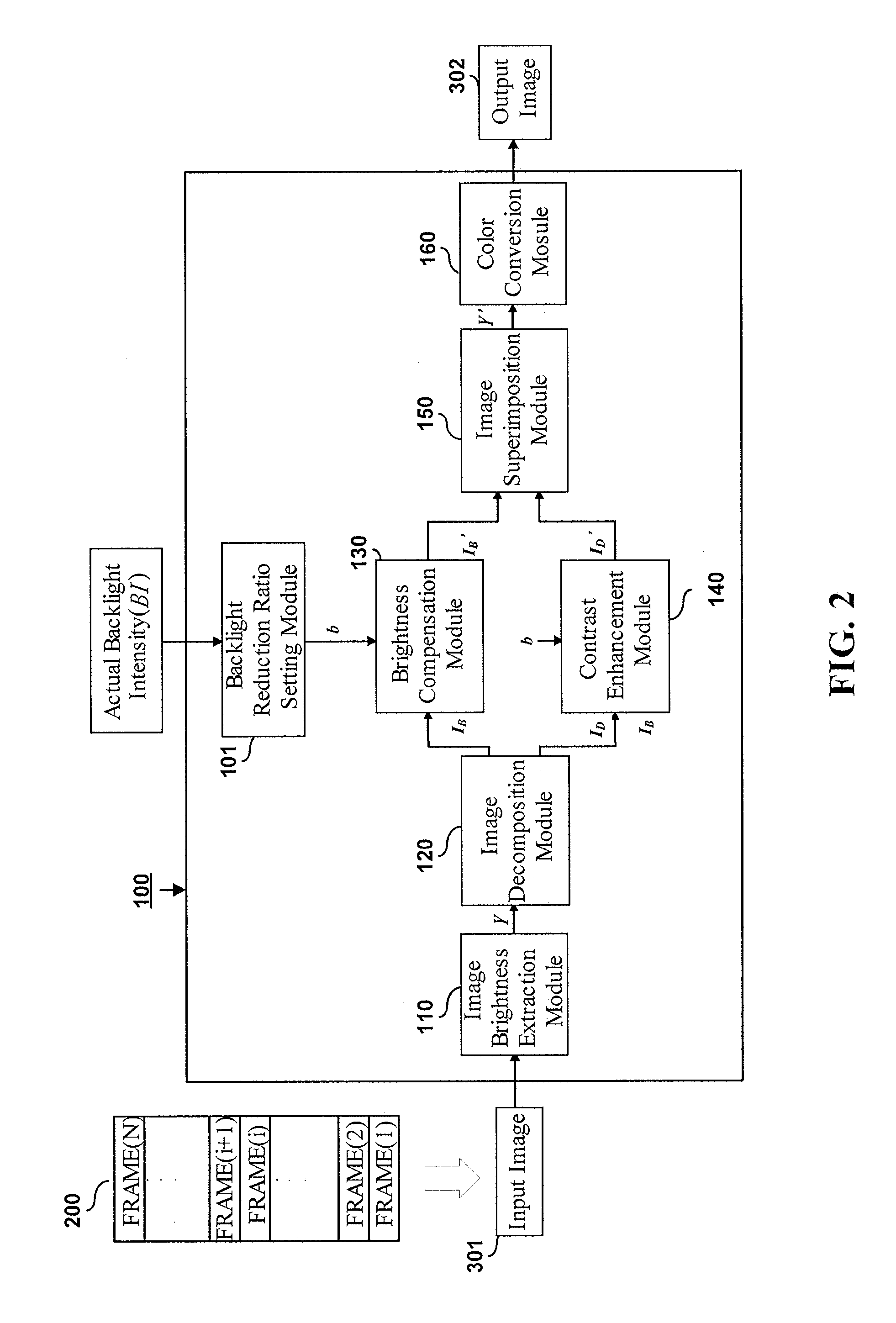
[0011]The low-backlight image visibility enhancement method and system according to the invention is characterized by the capability of firstly converting the image of each video frame into a brightness-based grayscale image; secondly decomposing the grayscale image into a low-pass base layer and a high-pass detail layer; thirdly performing a brightness compensation for the base-layer image and a contrast enhancement for the detail-layer image; and finally superimposing the two image layers into one single image and performing color conversion to the combined image. The resulted image is then used for display on the display unit. This feature allows the display unit to use a low level of backlight to save electrical power consumption while nevertheless allow the image to be displayed with good visibility to the user.

Problems solved by technology

However, since the backlighting module on TFT-LCD is used for light emitting, which is power consumptive, it will cause the battery to have a shortened life of use.
However, one drawback to this solution is that it would cause the displayed image to have a dimmed level of visibility to the user who might be unable to view the displayed image clearly.

Method used


Image

  • Low-backlight image visibility enhancement method and system
  • Low-backlight image visibility enhancement method and system
  • Low-backlight image visibility enhancement method and system

Examples


first embodiment

[0031]By the first embodiment, the image decomposition module 120 is implemented with a bilateral filter that is capable of providing a low-pass filtering function and a high-pass filtering function, wherein the low-pass filtering function is used to produce the base-layer image IB while the high-pass filtering function is used to produce the detail-layer image ID. This bilateral filter is based on principle and theory disclosed in the following technical paper “Fast bilateral filtering for the display of high-dynamic-range images”, authored by F. Durand et al and published on Proceeding of the 29th Annual Conference on Computer Graphics and Interactive Techniques, New York, 2002, pp. 257-266), so detailed description thereof will not be given in this specification.

second embodiment

[0032]By the second embodiment, as shown in FIG. 3, the image decomposition module 120 is implemented with the combination of a low-pass digital image filter 121 and a digital subtracter 122. The low-pass digital image filter 121 is capable of performing a low-pass filtering process on the luminance-based image Y to thereby produce a low-band digital image Y1, which can be implemented with the following 3×3 Gaussian low-pass filter:

 [121242121]

On the other hand, the digital subtracter 122 is capable of performing a subtraction process on the luminance-based image Y and the low-band digital image Y1 to thereby produce a high-band digital image Y2, where Y2=Y-Y1. The output image Y1 of the low-pass digital image filter 121 then serves as the base-layer image IB, while the output image Y2 of the digital subtracter 122 serves as the detail-layer image ID.

[0033]In performance comparison of the above two embodiments, the first embodiment is more time-timing in process since the bilateral ...


PUM


Abstract

A low-backlight image visibility enhancement method and system is proposed for integration to a backlit type of display unit, such as active matrix LCD (Liquid Crystal Display). The proposed method and system firstly converts the image of each video frame into a brightness-based grayscale image; then decomposes the grayscale image into a low-pass base layer and a high-pass detail layer; and then performs a brightness compensation for the base-layer image and a contrast enhancement for the detail-layer image; and finally combines the two image layers into one single image and performs color conversion to the combined image. The resulted image is then used for display on the display unit. This feature allows the display unit to use a low level of backlight to save electrical power consumption while nevertheless allow the image to be displayed with good visibility.

Description

BACKGROUND OF THE INVENTION[0001]1. Field of the Invention[0002]This invention relates to image processing technology, and more particularly, to a low-backlight image visibility enhancement method and system which is designed for use with a backlit-type of display unit, such as a TFT-LCD (Thin-Film Transistor Liquid Crystal Display) active matrix display unit, for visibility enhancement of the video images displayed on the display unit under a low-backlight condition.[0003]2. Description of Related Art[0004]TFT-LCD (Thin-Film Transistor Liquid Crystal Display) is a dot-matrix display technology widely utilized on various types of personal computers and portable electronic devices such as notebook computers and intelligent mobile phones. The TFT-LCD is equipped with an N×M dot matrix which is an array of N rows and M columns of pixels, wherein each pixel is capable of displaying a particular color or grayscale value in response to the charging of a particular level of data voltage th...

Claims


Application Information

Patent Timeline
IPC IPC(8): G09G3/36
CPCG09G3/3406G09G3/3648G09G2320/0626G09G2320/0646G09G2360/16G09G2330/021G09G2340/16G09G2360/145G09G2320/066
Inventor TSAI, PEI-SHANCHEN, HOMER H.LIANG, CHIA-KAI
Owner NAT TAIWAN UNIV
Learn More