Toner-fixer apparatus and electronic photograph printer

Inactive Publication Date: 2009-07-23
MIYAKOSHI PRINTING MACHINERY
View PDF5 Cites 4 Cited by
  • Summary
  • Abstract
  • Description
  • Claims
  • Application Information

AI Technical Summary

Benefits of technology

[0021]The hot air blown by the hot-air-blower section through the air ejection ports onto the web can be exhausted by the air exhaust section smoothly from between the apparatus main unit and the web since the toner-fixer apparatus according to the present invention has an air-exhaust section for suctioning air from the air exhaust ports having openings on the apparatus main unit opposed to the web.
[0022]Consequently, reliable air convention between the apparatus main unit and the web and reliable thermal efficiency provide time-saving and effective removal for the dried carrier liquid from the web and toner-fixing capability. The electronic photograph printer can maintain clean condition therein since the air-exhaust section capable of collecti

Problems solved by technology

However, the thermal roller method has limits in time and temperature when making contact between the rolls and a printed surface.
However, the aforementioned non-contact hot-air-fixer apparatus has the following problems.(a) The aforementioned non-contact hot-air-fixer apparatus is configured to discharge hot air from many through-holes provided on a plate-shaped heater component to make the hot air contact with the web.
Such incapability for circulating the hot air reduces thermal effic

Method used


Image

  • Toner-fixer apparatus and electronic photograph printer
  • Toner-fixer apparatus and electronic photograph printer
  • Toner-fixer apparatus and electronic photograph printer

Examples


Embodiment Construction

[0031]An example of a toner-fixer apparatus and an electronic photograph printer as an implementation of the present embodiment will be explained as follows with reference to drawings.

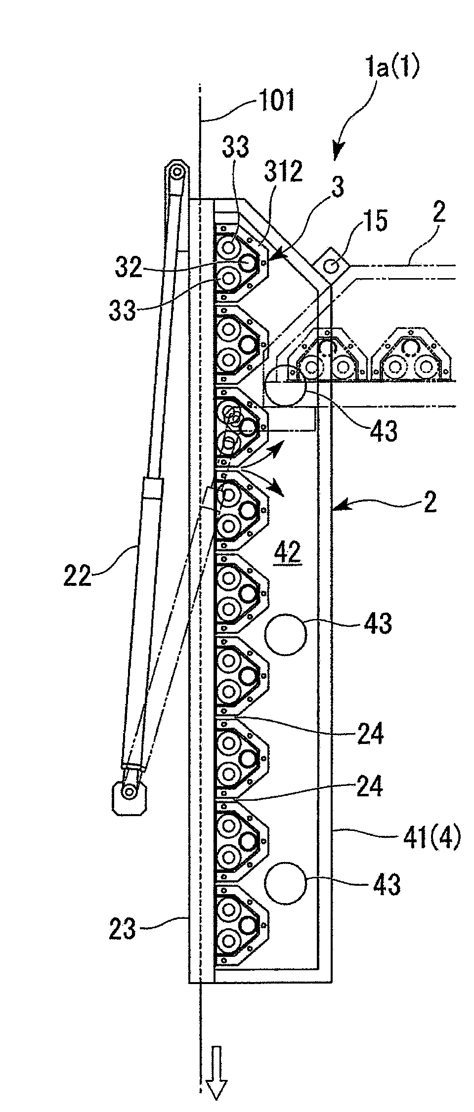
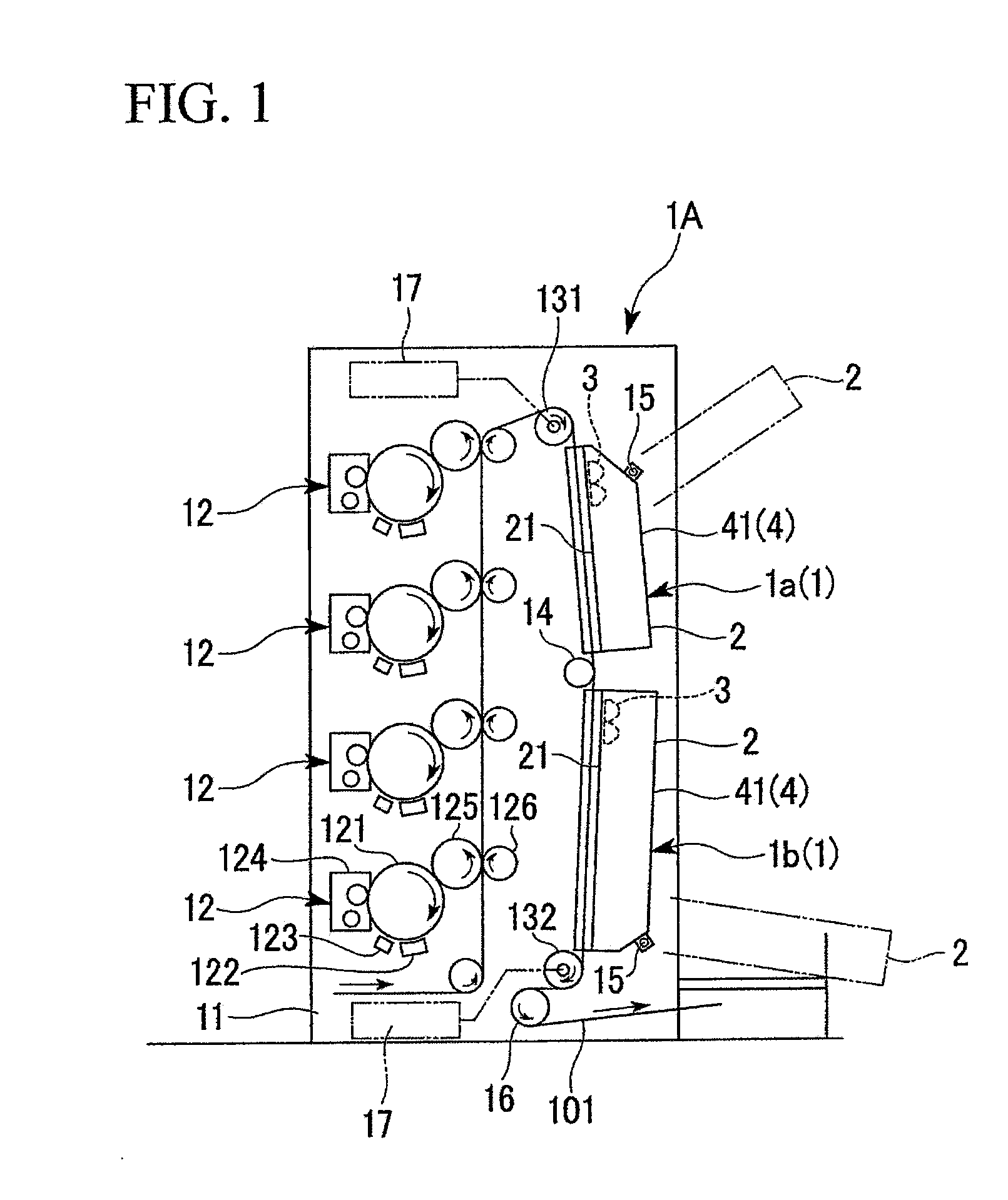
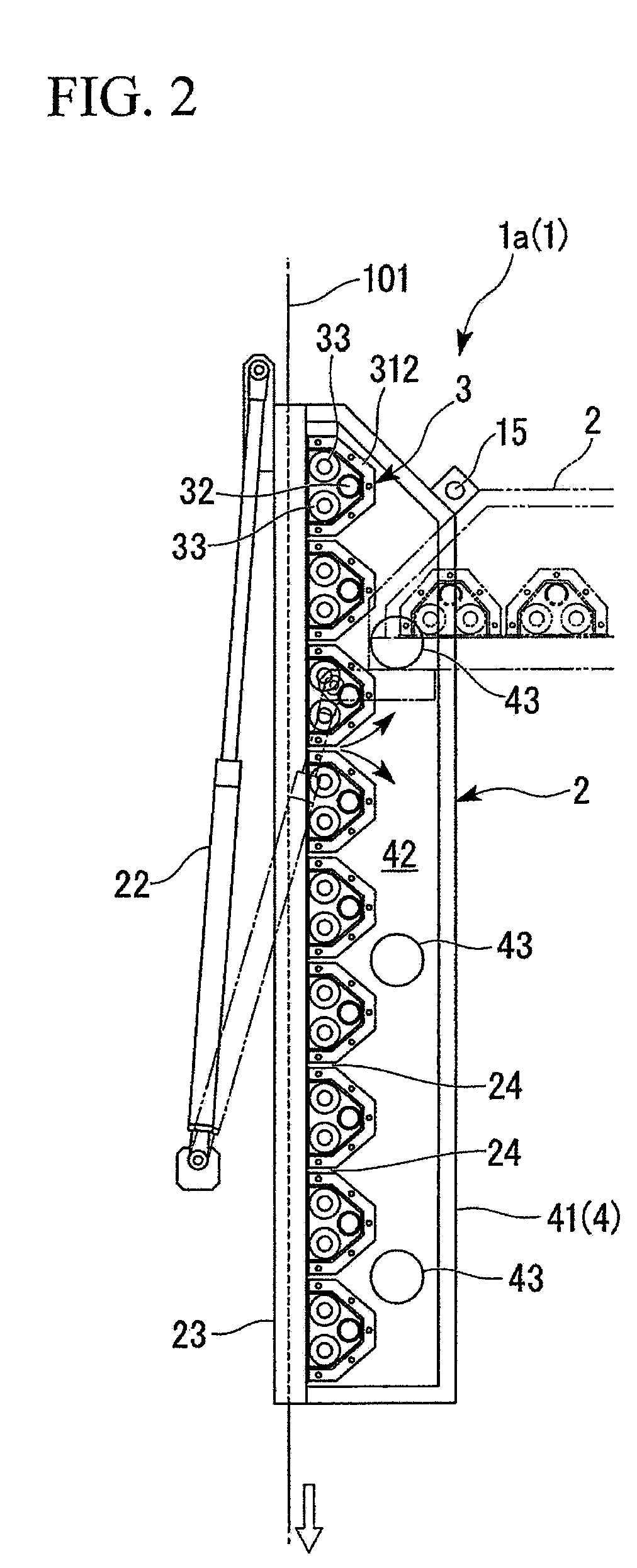
[0032]FIG. 1 is a front elevation showing an electronic photograph printer 1A adopting a toner-fixer apparatus 1 according to the present invention. FIG. 2 is a front elevation in cross section showing the configuration of an apparatus main unit 2 of the toner-fixer apparatus 1. FIG. 3 is a front elevation showing the web running vertically in the apparatus main unit. Hereinafter, this view indicates a web-opposing plane 21. FIG. 4 is a fragmentary enlarged view of FIG. 3. FIG. 5 is an enlarged view of the hot-air-blower unit 3 provided in an apparatus main unit 2.

[0033]The following explanation is based on the precondition that, in FIGS. 1 to 5, components shown in an upper section of the drawing is disposed at a somewhat distant location from a floor line, and components shown in a lower section of t...


PUM


Abstract

A toner-fixer apparatus 1 used in an electronic photograph printer includes: an apparatus main unit extending along a web fed in the electronic photograph printer; a hot-air-blower section having air ejection ports for blowing hot air onto the web; and an air-exhaust section for suctioning air into air exhaust ports having openings on the apparatus main unit opposed to the web. In this configuration, the toner-fixer apparatus obtains capabilities in terms of fixing toner used in a multi-color image, thermal efficiency, environmental load, and space saving.

Description

[0001]The present application is based on patent application No. 2008-009356 filed in Japan on Jan. 18, 2008, the content of which is incorporated herein by reference.BACKGROUND OF THE INVENTION[0002]1. Field of the Invention[0003]The present invention relates to a toner-fixer apparatus used in a wet electronic photograph printer using developing solution including liquid toner and carrier liquid, and in particular, the present invention relates to a toner-fixer apparatus and an electronic photograph having the toner-fixer apparatus provided therein for fixing an image onto a sheet on a sheet-transferring path by blowing hot air thereonto.[0004]2. Description of the Related Art[0005]In some image-forming systems using a developing solution including liquid toner (hereinafter called simply toner) and carrier liquid, a web absorbs the carrier liquid when a toner image transferred onto an intermediate-transfer component is further transferred onto the web. In a case of forming a multi-...

Claims


Application Information

Patent Timeline
IPC IPC(8): G03G15/20
CPCB41J11/002G03G2215/0658G03G15/2003F26B13/10
Inventor IZAWA, HIDEOSETOYAMA, JUNICHIKIKUCHI, NOBUYUKI
Owner MIYAKOSHI PRINTING MACHINERY
Why Eureka
Try Eureka